
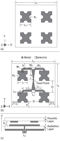
Figure 1 Stacked microstrip antenna array structure: parasitic layer (a), radiation layer (b), cross section (c).
A novel, two-layer, stacked, high gain, microstrip, cylindrical conformal antenna based on planar cross snowflake fractal patches exhibits high gain and aperture efficiency. Its impedence bandwidth is 19.75 percent, from 5.23 to 6.54 GHz, with a gain of 12.1 dBi and its corresponding aperture efficiency is 87.5 to 89.75 percent at 5.8 GHz. Measurement results agree closely with the simulation.
Conformal antennas have received wide interest in aerospace and wireless communication applications due to their aerodynamic properties and low radar cross section (RCS).1-2 Characteristics such as small volume, light weight and low profile, make the microstrip antenna a preferred choice.3 When conformed to a curved surface geometry, however, its electromagnetic properties and corresponding radiation patterns are strongly disturbed; the influence of mutual coupling and feed phase cannot be neglected.4-5 The problem of overcoming performance deficiencies in conformal antennas, with respect to array unit and aperture efficiency, has been well studied, with much theoretical analysis.6-16 The conformal finite difference time domain (CFDTD) method6 and discrete mode matching method (DMM)7-8 are often used to investigate and improve the electromagnetic properties of cylindrical conformal antennas.
Specific structures proposed to improve conformal antenna characteristics include the helix, meander-line and electromagnetic band gap (EBG).17-20 By combining the helix antenna and meander-line antenna, a broad bandwidth hybrid antenna with high radiation efficiency is realized.17 Use of an EBG achieves miniaturization with high gain.18 In this article, a novel, two-layer, stacked, high gain, microstrip, cylindrical conformal antenna based on planar cross snowflake fractal patches is described.21 Its parameters are optimized using the 3D full-wave finite element method (FEM). The influence of several factors on performance is analyzed, and both simulated and experimental results are presented.
Analysis and Simulation
As demonstrated by Jin et al.,21 a microwave planar antenna with 2 × 2 cross snowflake radiators demonstrates promising performance, such as high gain and aperture efficiency at its center frequency of 5.8 GHz. Its impedance bandwidth, defined as |S11| < ‐10 dB, is 22.9 percent, gain is as high as 12 dBi and its corresponding aperture efficiency is as much as 87.4 percent. Compared with rectangular array elements, the cross snowflake fractal antenna array reduces the required aperture size by 51 percent. The work described here uses the 2 × 2 cross snowflake fractal pattern antenna in a cylindrical conformal array to achieve high gain and aperture efficiency.
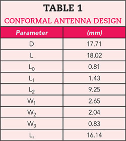
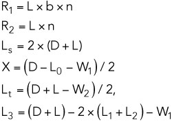
The sizes of the 2 × 2 cross snowflake radiators and cylindrical cavity can be determined based on a conventional two-layer, stacked, microstrip antenna array panel, as shown in Figure 1.21 The outer surface of a cylindrical cavity is fitted onto the parasitic layer, and the inner surface is fitted onto the radiation layer, forming a cylindrically shaped body. The geometric parameters and values of the conformal antenna design are shown in Table 1. The dimensions of the conformal antenna are given by
The initial size, L, of the single element square patch is obtained by
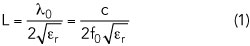
where λ0 is the free-space wavelength, c is the velocity of light in free space, εr is the relative dielectric constant of the substrate and f0 is the center frequency of the antenna.
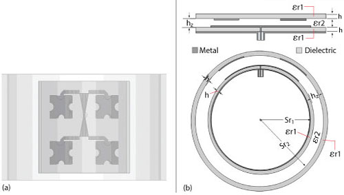
Figure 2 Top (a) and front (b) views of cylindrical conformal antenna.
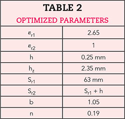
Based on the structure of the cylindrical conformal antenna, the original size of the panel antenna21 is adjusted and each parameter is optimized. Both the conformal antenna and the panel antenna realize the function of the coaxial feed with SMA connectors. Since the thickness of the layers directly affects the conformal profile and the thickness of the PTFE dielectric plate can make it difficult to bend with a relatively small radius, a dielectric plate with a thickness of 0.25 mm was chosen. Top and front views of the conformal structure are shown in Figure 2. The ratio of the upper and lower side patch unit is b, the fractal ratio is n, the inner diameter of cylinder is Sr1, the height of the air is hz, the permittivity of the layers is εr1, the dielectric permittivity of the air is εr2 and the layer thickness is h. The optimized parameters are summarized in Table 2.