
Vector network analyzers (VNA) provide some of the highest accuracy measurements of any RF instrument. However, poor-quality or defective test-port cables can significantly degrade measurement accuracy and represent a leading cause of VNA measurement problems. Using a VNA with poor-quality test-port cables is like pairing a quality audio receiver with cheap speakers—the speakers severely limit the sound quality. If you start with the most accurate VNA in the world and use poor-quality cables to connect to the device being tested, your measurement results will not be accurate.
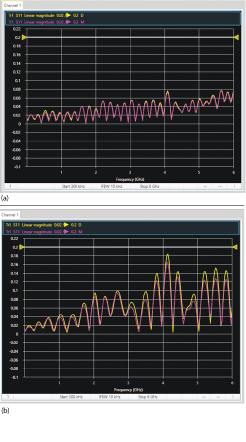
Figure 1 |S11| of a good (a) and bad (b) cable, straight (purple) and bent (yellow).
RF cables are used for most RF instruments, such as spectrum analyzers and signal generators. However, not all RF cables are suitable for VNA measurements. VNA users often grab whatever RF cable is lying around, not knowing the quality of the cable or they use semi-rigid or conformable coax cables because they are cheap and readily available. While semi-rigid or conformable coax cables work well at the beginning, they break down quickly with repeated use, as they are designed to be connected once and left in place. Conformable cables lose phase stability with just a few flexes, because the cable-connector interfaces are not reinforced at the junction, and the connector interface wears out after a few connections. At times, VNA users rely on the user calibration to make up for low-quality cables and adapters. While cable loss, phase and match are systematic errors, correctable with a calibration, any changes to these parameters behave like drift errors, which are not correctable. Any movement or reconnection after user calibration can introduce errors, reducing calibration stability and resulting in erroneous measurements.
If a cable is bad, the measurements most likely will be wrong. In manufacturing, this results in a good product being rejected or, even worse, a bad product passing. When designing an RF component, incorrect S-parameter data can lead to a costly design mistake. When impedance matching using the Smith chart, phase errors cause wasted time or may even reduce product performance, such as the transmission range of a wireless device. The potential technical problems from poor-quality cables include:
- Magnitude and phase errors in both reflection and transmission measurements, due to the phase drift of a cable, most often seen as ripples in the reflection and transmission magnitude
- Unstable or non-repeatable measurements
- Mechanical damage to the product or VNA port from damaged or worn out cable connectors.
For more insight into potential measurement errors introduced by cabling, we conducted an |S11| measurement on good and bad cables using a USB-based VNA. Figure 1 compares a good a cable (a) with a bad cable (b). The purple trace shows the measurement when the cable is straight, the yellow trace when the cable is bent. Bad cables show a larger change in the magnitude and phase when bent. A good cable has low reflections and minimal variation when bent.