

There has never been a better time to be talking about simulation of satellite transponders. These high flyers are incredibly expensive “pieces of kit,” not just to build but also to launch and operate. While there is a strong and concerted effort to drive down the cost of low orbit vehicles and to provide alternative fixed geo-position platforms, such as high-altitude platform stations (HAPS), still the majority of high data rate traffic is cornered by the multi-billion dollar geostationary “birds.” Using those for testing ground stations of any size does not make economic sense. The current alternative of convenient-to-use, comparatively low-cost satellite simulators has begun to have an impact on just about every SATCOM application, from commercial satellite news gathering (SNG), to in-flight internet connectivity, to military secure communications.
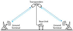
Figure 1 The AtlanTecRF MSS Multi-Path Satellite Simulator simultaneously talks to two sets of ground equipment, enabling the user to run extensive and prolonged tests without the need to go “live” on a satellite.
After addressing these markets with a range of products, AtlanTecRF is introducing the MSS Multi-Path Satellite Simulator, to tackle the needs of equipment manufacturers where the program requires delivery of portable, ground/mobile terminals as part of a civilian or defense communications network. This Simulator offers the capability to simultaneously test two terminals, proving the entire contract hardware with a minimum of satellite interaction. Figure 1 shows the MSS Multi-Path Satellite Simulator setup. The system talks to two sets of ground equipment simultaneously, enabling the user to run extensive tests without the need to go “live” on a satellite. The whole network can be set up to a deliverable state, with contract performance achieved in an extremely cost-effective manner.
Satellite Simulators in the MSS series consist of two interconnected modules (see Figure 2), each capable of communicating with a fixed or mobile terminal at either Ka-, Ku- or X-Band with the ability to vary the path attenuation, thereby reducing the real-world atmospheric effects. Taking the uplink or transmit (Tx) carrier from one ground-based system, the MSS re-transmits on the receive (Rx) carrier frequency for the downlink. But instead of sending the signal back to the same ground station, the MSS contacts a second ground terminal, completing the satellite link from point A to point B without any satellite being involved. The MSS Multi-Path Satellite Simulators accommodate the appropriate polarizations of the various carrier configurations, with horizontal and vertical being the most favored at Ku-Band and right- and left-handed circular the norm at Ka-Band.
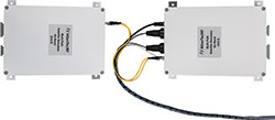
Figure 2 The MSS Multi-Path Satellite Simulator comprises two interconnected modules, each capable of communicating with a fixed or mobile terminal at Ka-, Ku- or X-Band. The Ka-Band version is shown.
Internally, the Satellite Simulator has the architecture of a high performance microwave frequency converter, which includes variable input attenuation to simulate the naturally-varying effective isotropic radiated power (EIRP) levels experienced in a typical 44,000 mile round-trip satellite link through the Earth’s atmosphere. The other variable parameter is the local oscillator (LO) frequency, which is adjustable to ensure coverage of every likely satellite transponder link. Control of the attenuation and frequency are achieved through AtlanTecRF’s proprietary digital control technology which, via Ethernet, provides the user with the choice of a PC graphical user interface or remote programmed control for automated test schedules. With such a Satellite Simulating Test System, the program provider can test multiple Tx and Rx paths over the full envelope of frequency regimes, gathering data to verify the deliverable performance criteria in a timely and cost-effective way.
The MSS Satellite Simulator Systems are typically supplied as a two-module set to point to each of a two-terminal communications link. Each module has waveguide horn antennas, of nominal 15 dB gain, whether of linear or circular polarization (see Figure 3). The internal input attenuator is controllable in 0.5 dB steps to 60 dB, while the frequency range of the LO enables all the standard operating bands to be explored. The base conversion is selectable through options from ‐20 to +10 dB. LO frequency stability is determined by either an internal, very high grade, low phase noise, oven-controlled crystal oscillator (OCXO) or from an input from the general system’s 10 MHz reference. Other optional features include phase shift and time delay, further emulating the true and likely conditions encountered in the application. Importantly, ease of use is key with no complex menu chains, rather a quick reacting setup and responsive controls.
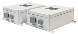
Figure 3 Side view of the Ka-Band Multi-Path Satellite Simulator, showing the antennas.
In addition to the issues of economics and speed, there may also be other critical considerations when employing this off-air testing using the MSS. If the projected use of the multi-location communications system is to carry confidential commercially or military information, there is much to be gained by carrying out link path testing in a secure environment, rather than in public on an open satellite transmission. This effectively deprives competitors or the enemy the heads-up on encryption techniques before real and vital data is sent. Also, by testing privately across the available Ka-, Ku- and X-Band spectrum, the actual frequencies to be used are not divulged, and the operator, once again, stays ahead of the game.
AtlanTecRF
Braintree, U.K.
www.atlantecrf.com