
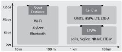
Figure 1 Universe of networking technologies.
Analysts from technology research firm Gartner are predicting a population of over 26 billion devices—excluding smartphones, tablets and computers—connected to the internet of things (IoT) by 2020. This volume of connected devices will require massive support from existing wireless networks. Among the mobile IoT (MIoT) technologies to be standardized by the 3rd Generation Partnership Project (3GPP), narrowband IoT (NB-IoT) represents the most promising low power wide area network (LPWAN) radio technology, enabling a wide range of devices and services to be connected using the cellular telecommunications bands (see Figure 1).
This article presents an overview of NB-IoT requirements, how they compare with LTE and the resulting challenges for component development. The use of simulation tools for system analysis and design is demonstrated using NI AWR Design Environment, specifically, Visual System Simulator™ (VSS) system design software. VSS test bench examples are presented, including NB-IoT signals operating in the same band as an LTE signal and in the guard band of an LTE signal.
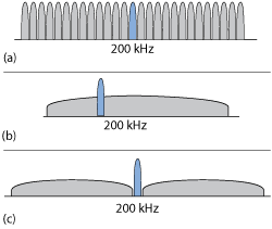
Figure 2 Deployment modes for NB-IoT: standalone GSM (a), in-band LTE (b) and guard-band LTE (c).
SYSTEM REQUIREMENTS
In release 13, the 3GPP specified a new radio air interface for MIoT applications. It focuses on improved indoor coverage, low-cost devices (less than $5 per module), long battery life (more than 10 years), massive connectivity (around 50,000 connected devices per cell) and low latency (less than 10 ms).
NB-IoT will enable operators to expand their wireless services to applications such as smart metering and tracking and will enable nascent opportunities such as “smart cities” and eHealth infrastructure. NB-IoT will efficiently connect these many devices using the existing mobile networks, adding small amounts of fairly infrequent two-way data, securely and reliably. The standard utilizes 180 kHz user equipment (UE) bandwidth for both downlink and uplink and can operate in three different deployment modes. As shown in Figure 2, these mode are:
- Standalone operation, in which a GSM operator replaces a 200 kHz GSM carrier with NB-IoT, re-farming dedicated spectrum in, for example, GSM EDGE radio access network (GERAN) systems. This is possible because both the GSM carrier’s bandwidth and the NB-IoT bandwidth, inclusive of guard band, are 200 kHz.
- NB-IoT inside an LTE carrier, where the operator allocates one of the 180 kHz physical resource blocks (PRB) to NB-IoT. The NB-IoT air interface is optimized for harmonious coexistence with LTE without compromising the performance of either.
- Guard-band deployment, utilizing the unused resource blocks (RB)within an LTE carrier’s guard band.
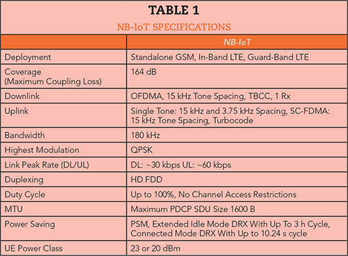
Table 1 shows the specifications for NB-IoT, which are quite different than the specifications for existing cellular technology. Where cellular technologies require large bandwidth with high data rates and low latency at the expense of lower device battery life, IoT requires robust data transmission with significantly lower data rates, long range coverage and long device battery life. While LTE uses bandwidths greater than 1.4 MHz, IoT communication can suffice with kHz bandwidths. Given these differences, using the existing GSM and LTE systems for IoT wastes spectrum and data rate. The introduction of a narrowband channel, such as 3.75 kHz, quadruples the number of connections in LTE’s traditional 15 kHz subcarrier spacing. Device cost is another factor differentiating mobile devices designed for voice, messaging and high speed data transmission from NB-IoT applications that require low speed and reliable data transfer. Many NB-IoT use cases require a low device price to be viable, as well as consideration of installation and potential risk of theft.
NB-IoT will heavily utilize LTE technology, including downlink orthogonal frequency division multiple access (OFDMA), uplink single carrier frequency division multiple access (SC-FDMA), channel coding, rate matching and interleaving. This is reducing the time to develop specifications and NB-IoT products by LTE equipment and software vendors. However, developing robust, low-cost and power-efficient IoT devices that handle low data rates with large area coverage is a departure from component design efforts driven by the different system requirements of cellular. As the following examples illustrate, RF system simulation can help solve these challenges and support the design and analysis of the UE modules, antennas, RF front-ends and wireless networks that will co-exist with NB-IoT and LTE signals.
IN-BAND IoT SIMULATION
The VSS project shown in Figure 3 simulates the operation of NB-IoT inside an LTE carrier. The NB-IoT uplink signal is configured as in-band, narrowband physical uplink-shared channel (NPUSCH) format 1 and compliant with the 3GPP release 13 specification. In this example, the NB-IoT signal is placed in an unused RB within the LTE band. The available NB-IoT examples in VSS enable studying in-band and guard-band operation modes.
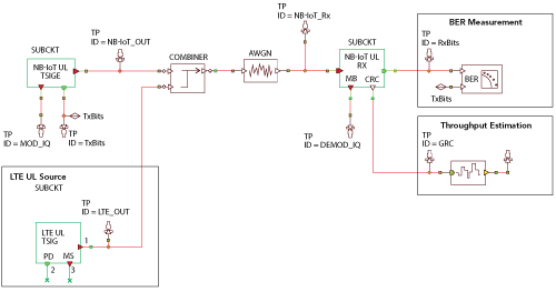
Figure 3 Test bench for the NB-IoT in-band uplink mode.
The NB-IoT uplink supports both multi-tone and single-tone transmissions. Multi-tone transmission is based on SC-FDMA, with the same 15 kHz subcarrier spacing, 0.5 ms slot and 1 ms sub-frame as LTE. SC-FDMA is an attractive alternative to OFDMA, especially in uplink communications. The lower peak-to-average power ratio (PAPR) greatly benefits the mobile terminal in transmit power efficiency, which extends battery life and reduces the cost of the power amplifier. Single-tone transmission supports two subcarrier spacing options: 15 and 3.75 kHz. The additional 3.75 kHz option uses a 2 ms slot and provides stronger coverage to reach challenging locations, such as deep inside buildings, where signal strength can be limited. The 15 kHz numerology is identical to LTE and, as a result, achieves excellent coexistence performance. The data subcarriers are modulated using π/2 binary phase shift keying (BPSK) and π/4 quadrature phase shift keying (QPSK) with phase continuity between symbols, which reduces PAPR and allows the power amplifiers to operate more efficiently (saturated). The number of 15 kHz subcarriers for a resource unit can be 1, 3, 6 or 12, supporting both single-tone and multi-tone transmission of the uplink NB-IoT carrier, with a total system bandwidth of 180 kHz (up to 12, 15 kHz subcarriers or 48, 3.75 kHz subcarriers).
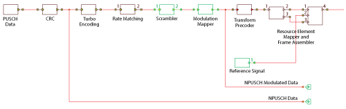
Figure 4 NPUSCH encoder simulated in VSS.
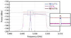
Figure 5 NB-IoT and LTE spectra for the in-band mode.
The NB-IoT uplink physical channel includes a narrowband physical random access channel (NPRACH) and NPUSCH. The NPRACH is a new channel designed to accommodate the NB-IoT 180 kHz uplink bandwidth, since the legacy LTE PRACH requires a 1.08 MHz bandwidth. Random access provides initial access when establishing a radio link and scheduling request and is responsible for achieving uplink synchronization, which is important for maintaining uplink orthogonality in NB-IoT. The NPUSCH supports two formats. Format 1 carries uplink data, supports multi-tone transmission and uses the same LTE turbo code for error correction. The maximum transport block size of NPUSCH format 1 is 1000 bits, which is much lower than that in LTE. Format 2 is used for signaling hybrid automatic repeat request (HARQ) acknowledgements for narrowband physical downlink shared channel (NPDSCH) and uses a repetition code for error correction. In this case, the UE can be allocated with 12, 6 or 3 tones. The 6 and 3 tone formats are introduced for NB-IoT UEs that, due to coverage limitations, cannot benefit from the higher UE bandwidth allocation.
A VSS simulation of NPUSCH encoding is shown in Figure 4. This sub-block generates a pseudo-random binary sequence, which undergoes cyclic redundancy check (CRC) followed by turbo encoding and rate matching for uplink LTE transmissions. Sub-block interleaving is performed on the bit stream out of the encoders. For each code word, all the bits transmitted on the physical uplink shared channel in one sub-frame are then scrambled with a UE-specific scrambling sequence prior to the modulation mapping, which has been selected by the system developer through the configuration options.
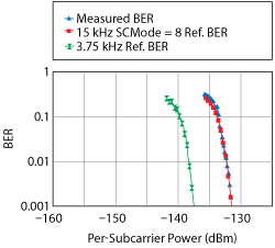
Figure 6 Simulated BER for the NB-IoT signal passed through AWGN channel model.
SC-FDMA can be interpreted as a linearly pre-coded OFDMA scheme, in the sense that it has an additional discrete Fourier transform (DFT) processing step preceding the conventional OFDMA processing. A DFT is performed by the transform pre-coder before the NPUSCH channel is multiplexed with the reference signal subcarriers (either single- or multi-tone) by first mapping them to the appropriate physical resources and then to the orthogonal frequency-
division multiplexing (OFDM) symbols and slots within each frame. Much like OFDMA, SC-FDMA divides the transmission bandwidth into multiple parallel subcarriers, maintaining the orthogonality of the subcarriers by the addition of the cyclic prefix (CP) as a guard interval. However, in SC-FDMA, the data symbols are not directly assigned to each subcarrier independently, as in OFDMA. Instead, the signal that is assigned to each subcarrier is a linear combination of all modulated data symbols transmitted at the same time instant. The difference between SC-FDMA transmission and OFDMA transmission is an additional DFT block before the subcarrier mapping.
A similar set of blocks is used to generate the LTE signal, which is then combined with the NB-IoT waveform, passed through an additive white Gaussian noise (AWGN) channel and terminated in an NB-IoT UL receiver for demodulation and decoding of the physical uplink shared channel (PUSCH) signal. For component and system designers, the AWGN channel model can be replaced with a different channel model or device under test (DUT).
The test bench in this in-band simulation has been configured to monitor the Tx signal spectrum at various points in the link (see Figure 5), the NB-IoT link performance in the presence of the LTE UL signal, I/Q constellation of the transmitted and demodulated signals, bit error rate (BER) (see Figure 6), block error rate (BLER), throughput (see Figure 7) and the CRC error for each block.
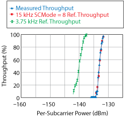
Figure 7 Simulated throughput for the in-band NB-IoT mode.
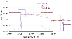
Figure 8 NB-IoT and LTE spectra for the guard-band mode.
GUARD-BAND NB-IoT SIMULATION
A related example demonstrates operation of NB-IoT in the guard band of an LTE signal. The project is essentially the same as in the previous example with a simple change to the NB-IoT RB location. For guard-band operation, the NB-IoT RB is set to be greater than zero or greater than N_RB_UL, the upper limit, to operate in the lower or upper guard band, respectively. In-band operation is obtained by setting the NB-IoT RB at any value between these limits. The spectra for an NB-IoT channel operating in guard-band mode is shown in Figure 8.

Figure 9 Test bench with power amplifier (a) and guard-band mode spectra (b).
As previously mentioned, a front-end module, power amplifier and antenna design can be added to or substituted for the AWGN channel model, which serves as a placeholder for a DUT. Figure 9 shows an amplifier inserted between the UL transmitter and receiver. The simulation allows designers to sweep various parameters, such as input power, or toggle different NB-IoT subcarrier modulation schemes (π/2 BPSK or π/4 QPSK) to investigate the impact on performance, such as error vector magnitude (EVM).
CONCLUSION
The NB-IoT standard specified in 3GPP release 13 leverages the existing LTE network to support a future ecosystem of low-cost IoT devices. While the use of the existing LTE infrastructure with relaxed performance requirements, due to the lower data rates, will help offset some design challenges, the need for low cost, increased coverage area and longer battery life with sustained reachability introduces some difficult-to-achieve requirements. VSS and other system simulation tools aid NB-IoT system development by simulating designs pre-silicon, saving valuable time and effort bringing these new products to market.