
Behind the high speed data, communications and computing developments of recent decades, the need to characterize high frequency interfaces, devices, multi-path interconnects and antennas has proliferated dramatically. Once the domain of an elite few, these microwave measurements have migrated out of the laboratory, away from the specialist, into the lives of technicians, educators, researchers, doctors, manufacturers, inspectors and repairers across a plethora of industries. Increasingly used by non-specialists and systems integrators, microwave measurement needs to be straightforward, convenient, accurate, fast, compact, portable and affordable, as well as supporting proliferating applications and technologies such as 5G, IoT, radar and tissue and materials imaging.
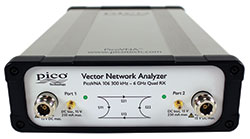
Despite its core measurement role, vector network analysis has clung to the bounds of the expert user and the deep pockets of established business, stubbornly refusing to fall within easy reach and adoption of the wider markets, embedded applications and the less familiar user. Fortunately, Pico Technology has risen to the challenge and produced the PicoVNA 106—a USB-controlled, professional and laboratory grade 300 kHz to 6 GHz vector network instrument that offers performance, portability, ease of use and affordability.
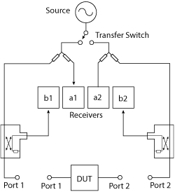
Figure 1 Quad RX architecture, including bias tee blocks.
Despite its simple form, small footprint and low cost, the instrument boasts a full-function, minimal-error, four-receiver architecture named “Quad RX.” This supports both 8- and 12-term calibration with none of the uncorrectable errors, delays and possible fragilities of traditional three receiver arrangements that do not remove switch errors. The PicoVNA 106 enables convenient calibration methods such as “enhanced isolation correction” and use of the “unknown thru.”
The highly compact PicoVNA 106 boasts a dynamic range of up to 118 dB at 10 Hz and only 0.005 dB RMS trace noise at its maximum operating bandwidth of 140 kHz. It can also gather all four S-parameters in just 190 µs per frequency point—a 500 point 2-port S2P Touchstone file compatible with test, math, view and electronic design automation (EDA) simulation tools in less than a tenth of a second. This performance is claimed to be competitive with expensive instruments, yet its low price means the PicoVNA 106 could be considered as a cost-attractive, high dynamic range scalar network analyzer or a highly competitive single-port vector reflectometer, let alone the full, dual-port, dual-path vector network solution that it actually is!
This makes the solution affordable in the classroom, for small business and even the amateur workshop, yet competent to meet the needs of all, right up to the microwave laboratory engineer and expert. Often excluded from lower cost models, bias tees are included for convenient injection of test bias or stimulus. Figure 1 shows the Quad RX architecture.
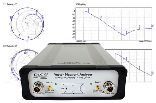
Figure 2 PicoVNA 106 with PicoVNA 2 software.
Readily hand carried or stowed, the PicoVNA 106A’s small size, weight and cost and its high performance make it suitable for field service, installation test, embedded and training applications. Its remote automation interface suits it to test automation, perhaps as a reflectometry or transmission measurement core for embedded roles. Test environments include broadband interconnect, cable and harness, antenna, component and subsystem assembly, installation and fault-over-life monitoring, as well as the manufacturing, calibration, distribution and service industries. Scientific applications extend into the materials, geological and life sciences and to food and tissue imaging and penetrating scans.
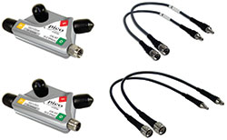
Figure 3 Calibration standards and test leads.
FUNCTIONALITY and ACCURACY
The PicoVNA 106 comes with all the functionality and versatility that would be expected from a modern vector network analyzer (VNA), comparable to or beyond more costly USB instruments and the even more costly and bulky benchtop options.
The VNA is supplied with Windows software that outputs in one, two or four measurement channels all the familiar measurement and plot formats to be expected for the four dual-port S-parameters or the two single-port parameters: logarithmic and linear magnitude and phase, real and imaginary, Smith and linear polar, SWR and group delay (see Figure 2). These can be saved or exported in various graphic and tabular formats, including Touchstone, for compatibility with a wide variety of viewers, domain converters, math and EDA simulation applications.
Pico Technology’s VNA software also includes Fourier transformation to the time domain. This adds convenient distance-to-fault capability or pulse response determination. In all cases, nominal impedance transformation is available (10 to 200 Ω), mathematical or via port matching pads and comprehensive limits tests can be applied to the cartesian plot formats.
Unwanted measurement contributions from feed lines, probes or test jigs can be eliminated using manual or automatic reference plane offset, including fully independent offset for each S-parameter when required. Alternatively, independent networks can be embedded or de-embedded at each port from a Touchstone representation of each—measured or synthesized. Unusual for any VNA, embedding or de-embedding is interpolated when measurement and network datasets do not share the same frequency points.
The company has also included in its PicoVNA 2 software two utilities to tackle the often complex distortion measures of gain compression and AM to PM. Both of these use a port power sweep at each test frequency, and both measurements are extracted using second-order interpolation. The company is maintaining its long-held tradition of free software provision. All features are included without additional charge, and this will extend to future enhancements and upgrades.
Addressing test leads and calibration standards, Pico offers PC3.5 and SMA male and female test ports using flexible and flex-formable, phase and flatness stable test leads. Four mating calibration standards, with traceable data, are assembled into convenient male and female SOLT housings. Figure 3 shows the calibration standards and test leads. Like the test leads, the SMA and PC3.5 calibration standards all use robust, high-precision stainless steel connectors.
Pico Technology
St Neots, U.K.
www.picotech.com