
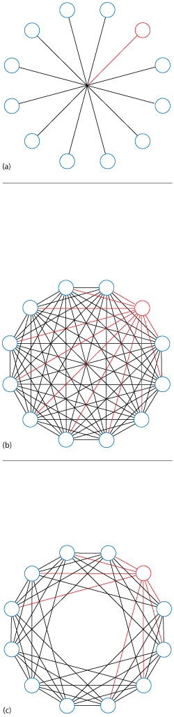
Figure 1 12-port fan-out configurations: hub (a) full (b) and LC8 (c).
During the past 10 years, the use of military radios has increased dramatically—so has the need to test those radios. This stems from the advent of such military-based communication applications as the land mobile radio and tactical networks, as well as the introduction of both software defined radios and cognitive/multi-user multiple-input-multiple-output (MIMO) wireless radios. Typically, these military radios are tested together in a closed mesh network, with programmable attenuators used to vary the attenuation and simulate different distances between the radios. While this test platform (i.e., military radio testbed) enables test engineers to conduct rigorous, transparent and replicable testing, it has limitations: the size of the mesh network or the number of radios that can be tested together.
For test engineers wanting to build their own testbed with individual components, JFW provides the necessary programmable attenuators and the power divider/combiners to be cabled together. JFW also provides RF test systems with the components already packaged together with a computer interface for an all-in-one solution. These test systems are available in three different configurations, depending on how many military radios test engineers want to test together. The result is a comprehensive approach to quickly and successfully test modern military radios.
TESTBED OPTIONS
JFW offers three different test setups for testing military radios: hub, full and limited fan-out (see Figure 1).
Hub Fan-Out
Most test engineers building military radio testbeds use a hub design to create a mesh network in which each radio is able to communicate with the entire network at one power level (see Figure 1a). The other ports must adjust their own attenuation to the mesh to receive the input radio at the desired power. The hub fan-out design utilizes a resistive divider/combiner with a star matrix configuration to combine all ports through a central hub. The star configuration limits the number of paths in the matrix to equal the number of ports. Each port has a single programmable attenuator that can be remotely controlled to simulate static or dynamic environments. The hub fan-out design can be used for radio-to-radio communication testing up to 18 radios. Because of the lower number of programmable attenuators—no more than 18—it is much lower in cost than the other two options.
Full Fan-Out
For testing between 19 and 32 radios up to 3 GHz, the simple hub fan-out design is not viable. Instead, a test system based on a full fan-out design is recommended (see Figure 1b). The full fan-out design is constructed as a fully meshed matrix with a path between every pair of ports, each path having its own individually controlled programmable attenuator. The attenuators enable the test engineer to set a different setting for each path through the matrix. The attenuation values can be faded over time to simulate signal fading between radios. Each port can be connected to a device (e.g., a radio or handset) that can transmit/receive signals. Most JFW test systems utilizing this design cover either 30 to 3000 MHz or 500 to 6000 MHz.
Compared to the hub fan-out design, the full fan-out design uses a reactive, rather than a resistive, combiner/divider. This allows the full fan-out design to test more radios—up to 32 radios or ports—simultaneously. The design also offers the maximum signal fading flexibility. Because it allows every path to be set to a unique attenuation, the full fan-out is ideal for testing radio-to-radio communication. However, this is the most expensive of the three configurations, as the number of attenuators scales quadratically with the total number of radios.
Limited Fan-Out
To test more than 32 radios up to 3 GHz, the limited fan-out design is the best option. With this configuration, each port connects to only “L” number of its neighboring ports, where the number of neighboring ports depends on the application (see Figure 1c). The limited fan-out design is particularly useful for reducing the size and cost of testing a large number of ports. By reducing the number of internal paths through the matrix, the size and cost of the test system is reduced. The reduced number of internal paths allows a greater number of ports to be offered, meaning that more radios can be tested simultaneously.
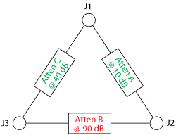
Figure 2 With the full fan-out configuration, a unique attenuator on each path maximizes flexibility for radio-to-radio testing.
Where a full fan-out design with 48 ports requires 1,128 programmable attenuators, a limited fan-out LC16 design for 48 ports requires only 384 programmable attenuators. For this case, the difference in cost and size between the full fan-out and limited fan-out designs is roughly 66 percent. JFW currently offers limited fan-out models with up to 40 ports, although designs with up to 64 radios or ports are possible.
IDENTIFYING THE LIMITATIONS
The hub fan-out design is limited by utilizing a resistive divider/combiner, which effectively limits the number of radios that can be tested together. In JFW’s case, two different types of hub fan-out transceiver test systems are offered. The largest resistive divider/combiner with a star configuration is an 18-port model that covers DC to 3 GHz, limiting the number of radios that can be tested together to 18. The largest JFW resistive divider/combiner with a star configuration is a 12-port model that covers DC to 6 GHz, limiting the number of radios that can be tested together to 12. The hub fan-out design is also limited by not being able to set every possible path to a desired attenuation. To illustrate, Figure 2 shows a full fan-out with port-to-port attenuation settings of 40, 10 and 90 dB. Figure 3 shows the hub fan-out, which cannot replicate the 40, 10 and 90 dB path settings.
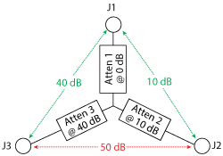
Figure 3 The hub fan-out cannot match the full fan-out’s 40, 10 and 90 dB attenuator settings.
In the case of the full fan-out design, the limitation is the size of the test system, which is limited to 32 radios or ports. With this design, a connection is required from any port to any other port. For 32 ports, a total of 496 internal paths are required, with each path containing a programmable attenuator. The 32-port full fan-out model offered by JFW occupies an entire 19 inch rack.
For the limited fan-out design, the limitation stems from the design. “Limited” in the phrase “limited fan-out” means not every port is connected to all other ports. In Figure 1c, each port is only connected to its eight neighboring ports. For a transmission on port 1 to reach port 9, it would have to be repeated by one of the radios that can see both ports 1 and 9—in this case, the radio connected to port 6.
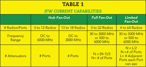
Table 1 summarizes the limitations and abilities of each of the three designs and JFW’s current capabilities. The relative cost and size can be estimated by the number of attenuators used in each type.
Testing as many military radios together as possible is a key goal for radio testing. There are three test setups that can be employed, each with its limitations. For testing up to 18 radios, the hub fan-out is the best option. When testing up to 32 or 64 radios, a full fan-out or limited fan-out design, respectively, should be used. For maximum flexibility, some applications may require every unique path to have its own attenuation, requiring the full fan-out configuration.
JFW Industries Inc.
Indianapolis, Ind.
www.jfwindustries.com