
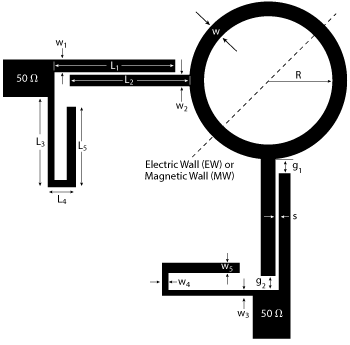
Figure 1 Configuration of a dual-band bandpass filter using a single Q-CRR.
A dual-band bandpass filter with multiple controllable transmission zeroes (TZ) and wide stopband performance is based on a single quadruple-mode circular ring resonator (Q-CRR). The two passbands are generated by using degenerate modes. After installing two parallel-coupled feed line sections on a ring at the two ports with 90 degrees separation and two open-ended tri-section stepped-impedance resonators (OT-SIR) loaded on the I/O ports, eight TZs are produced in the stopband. By tuning the length and the impedance ratio of the OT-SIR and the length of the parallel-coupled feed lines, the locations of the TZs are adjusted. Measured results show good agreement with simulation.
Dual-band bandpass filters (BPF) with good selectivity and wide stopbands are highly desired in modern dual-band wireless communication systems.1,2 Various design approaches have been used. Microstrip ring resonators have been employed in microwave circuits such as filters, mixers and oscillators.3,4 A dual-band ring resonator bandpass filter, can be realized by using coexisting degenerate orthogonal modes.5,6 Due to their compact size, high-Q factors and sharp rejection skirts, ring resonators have been comprehensively analyzed. Two dissimilar ring resonators with different resonant frequencies can be used to achieve dual-band passband performance, although the stopband is narrow and the size is relatively large.7-9 Dual-band BPFs have been designed using multilayer structures; however, a complex feed is usually required.9,10 Huang et al.,11 describe a dual-band bandpass filter using stepped-impedance ring resonators with an adjustable first- and second-order resonator; however, there is only a single transmission pole in the second passband, while the isolation between the two passbands and the suppression of the stopband are not good because there are only three TZs. Dual-band BPFs using ring resonators loaded by open-circuited stubs do not have sharp rejection skirts and good rejection in the stopband because there are only two TZs.12-15 Luo et al.,5,6 report on a class of dual-mode dual-band ring resonator BPFs using microwave C-sections, but these structures need many perturbation elements to be installed along the ring. Chiou et al.,16 describe a dual-band bandpass filter with four TZs based on a signal ring resonator, however, the upper stopband is narrow and this structure also needs many perturbation elements installed along the ring. Dual-band BPFs using a single rectangular ring resonator exhibit poor out-of-band rejection and selectivity.17
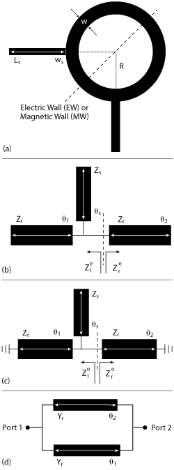
Figure 2 Q-CRR layout (a), even mode equivalent circuit (b), odd mode equivalent circuit (c), circuit for obtaining TZ frequencies (d).
In this article, we describe a dual-band BPF using a single Q-CRR. After installing two coupled-line sections at the two excitation ports, two transmission poles are generated in each passband. With a two-port excitation angle of 90 degrees, parallel-coupled feed lines and OT-SIRs at the I/O ports, eight controllable TZs are generated and provide a good isolation and a wide upper stopband. By tuning the length and the impedance ratios of the OT-SIRs, TZ locations are adjusted, extending the upper stopband.
FILTER DESIGN
Figure 1 shows the filter configuration. It consists of a quadruple-mode circular ring resonator (Q-CRR) connected to parallel-coupled feed lines and OT-SIRs loaded at the input/output (I/O) ports.
Q-CRR
The Q-CRR (see Figure 2a) consists of a circular ring resonator with two orthogonally separated open-ended stubs, where R, w and ws are the radius and the widths of the circular ring and open stubs, respectively. The operating mechanism is discussed by using even and odd mode analysis because of the resonator’s even symmetrical structure. The even and odd mode equivalent circuits are shown in Figures 2b and 2c. Zs and θs are the characteristic impedance and the electrical length of the loaded open-circuited stub on the ring. Zl and Zr represent the two oppositely oriented input impedances at the same position. The input impedances with superscript “e” and “o” are the even and odd mode impedances, respectively. According to transmission line theory and the odd-even mode analysis method, the resonant frequencies under even and odd mode excitation satisfy18

Due to transverse interference between the two signal paths from one port to the other port, some TZs are generated.19 Figure 2d is the equivalent circuit. The TZ frequencies are obtained by applying Y21 = Y12 = 0, where the admittance matrices are calculated by adding upper and lower Y-parameters of the two paths connected in shunt between ports 1 and 2. The calculated results are expressed by
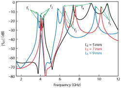
Figure 3 Simulated transmission response of the Q-CRR with different line length (Ls) under loose coupling.

where θ2 = 3θ1; so, the TZs appear at θ1 = (2n-1)×90°, n = 1, 2, 3,……
Figure 3 shows the frequency responses of the Q-CRR with loose coupling for various values of LS. It can be seen that all the resonant frequencies become smaller as LS increases. The first two resonant frequencies, f1 and f2, split from each other as LS increases, while the third and fourth resonances, f3 and f4, move closer to each other and thus form a second passband. The fifth resonance f5 is the first spurious frequency.
Parallel-Coupled Feed Lines
Figure 4a shows the layout of Q-CRR dual-band BPF fed by the parallel-coupled feed lines. L1, w1 and L2, w2 are the length and width of the parallel-coupled feed line connecting with input/output ports and the loaded open stub on the circular ring resonator, respectively, while s is the gap between the two coupled lines.
To examine their characteristics, the parallel-coupled feed line structure shown in Figure 4b is simulated with three different values of L1. The results are shown in Figure 4c. When L1 = L2 and w1 = w2, the TZs are distributed in the stopband. The TZs shift lower in frequency when the length of L1 increases. The transmission zero f’Tz2 is changed significantly by altering the length of L1 while leaving the length of L2 unchanged (see Figure 4d), while f’Tz1 varies slightly.
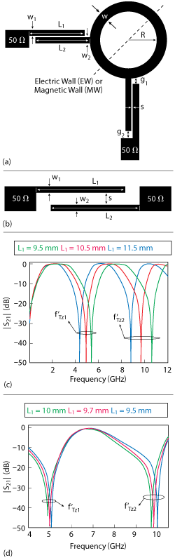
Figure 4 Q-CRR layout (a), parallel-coupled feed line (b), simulated |S21| for the parallel-coupled feed lines using three values of L1 in the case of L1 = L2 and w1 = w2 (c), variation of TZs vs. length of L1 (d).
The effect of these overlaps is seen when the circular ring resonator and the parallel-coupled lines are used together. Figure 5 shows the simulated results of the Q-CRR fed by the parallel-coupled feed lines with three different lengths of L1. The TZ overlap shown in Figure 5 causes suppression of the fifth resonant frequency in Figure 3, and produces sharper rejections at cutoff regions, further extending the upper stopband.
TZs Introduced By Stub-loaded OT-SIR
Figure 6 shows the OT-SIR consisting of three sections. The impedance ratios (K1, K2) and the length ratios (α, γ, ζ) are defined respectively as K1 = Z1/Z2, K2 = Z1/Z3, and α = θ1/(θ1+θ2+θ3), γ = θ2/(θ1+θ2+θ3), ζ = θ3/(θ1+θ2+θ3). The input impedance of the OT-SIR is

when the Zin= 0, the first three TZs of the OT-SIR are obtained.
To verify the design concept, a resonator is simulated on a substrate with relative dielectric constant of 3.5 and thickness of 0.508 mm. Two microstrip lines with 50 Ω characteristic impedance are utilized to feed the OT-SIR. The length is fixed at 19.5 mm, corresponding to λg/2 at the fundamental resonant frequency, where the λg is guided wavelength, while the length ratios α = ζ. Figure 6 shows the simulated result of normalized TZs fTZi /fTZ1 (i = 1, 2, 3) versus the length ratio γ under the condition of (K1 = 0.3, K2 = 0.4) and (K1 = 0.8, K2 = 0.5). The gaps between the first three TZs are tuned by altering the impedance ratios K1 and K2 and the length ratio γ̣ The adjustment of K1 can be used to enlarge the spans between the first three TZs, for example, as the K1 increases, the spacings between the first three TZs decrease. Similarly, the spans between the three TZs become smaller when the impedance ratio K2 is enlarged. It is also apparent that the spans between the first three TZs decrease when the length ratio γ increases. The relationship of the spans between the first three TZs and the length ratios α and ζ can also be seen by using the same method. Changes in the length ratio ζ have similar effects as changes in the length ratio γ, while the spans between the first three TZs become larger as the length ratio α increases. So, the location of the TZs can be adjusted by tuning the impedance ratios (K1, K2) and the length ratios (α, γ, ζ), which improves selectivity and rejection in the stopband.
EXPERIMENTAL RESULTS
The dual-band BPF with multiple controllable TZs is fabricated on Taconic RF-35 substrate with relative dielectric constant of εr=3.5 and thickness of h = 0.508 mm. The dimensions are L1 = 10.26 mm, L2 = 10.4 mm, L3 = 10 mm, L4 = 2.74 mm, w1 = 0.12 mm, w2 = 0.24 mm, w3 = 0.24 mm, w4 = 0.26 mm, w = 0.6 mm, g1 = 0.49 mm, g2 = 0.3 mm, s = 0.21 mm and R = 6.75 mm. A photograph of the filter is shown in Figure 7a. It is measured with a Keysight 8757D network analyzer. Simulated and measured frequency responses are compared in Figure 7b. Good agreement is achieved. The measured minimum insertion loss is 1 dB in the first passband and 1.4 dB in the second passband. The 3 dB fractional bandwidths are 20 percent and 11.5 percent, respectively. Passband return losses are larger than 13.6 dB in the first passband and 18 dB in the second passband. Eight TZs are generated at 0.32, 2.31, 4.32, 4.75, 6.73, 7.12, 10.92 and 11.44 GHz, respectively. The TZs located at 0.32, 4.32 and 10.92 GHz are generated by the parallel-coupled feed lines, the TZs of 2.31, 6.73 and 11.44 GHz are generated by the OT-SIR and the others are achieved through transverse interference of the Q-CRR. With the aid of additional controllable TZs provided by the parallel-coupled feed line section and the loaded OT-SIR, the fifth resonance located in the upper stopband is fully suppressed. Meanwhile, the span of the upper stopband is also enlarged. In the measured upper stopband response, 20 dB rejection in the frequency range of 6.5 to 12.25 GHz is obtained.
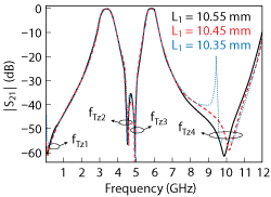
Figure 5 Simulated |S21| for the Q-CRR fed by the parallel-coupled feed line vs. length of L1.
CONCLUSION
A dual-band BPF with multiple controllable TZs using a single Q-CRR and a pair of OT-SIRs is presented. Two TZs are placed between the two passbands and six TZs are created in the stopband which results in a good selectivity and a wide upper stopband. Two transmission poles are generated in each passband after installing two parallel-coupled-line sections at the two excitation ports. The spurious frequency at the fifth resonance of the resonator is suppressed by an additional zero from the parallel-coupled-line section. When the TZs generated by the Q-CRR are combined with the TZs introduced by the stub-loaded OT-SIR and parallel-coupled feed lines, performance in the upper stopband is improved.
ACKNOWLEDGMENT
This work is partially supported by the R&S program for science and technology innovation, partially by National Key Scientific Instrument and Equipment Development Projects (Grant No. 2013YQ200503), partially by the National Natural Science Foundation of China (Grant No: 61271026) and partially by the Program for New Century Excellent Talents in University (Grant No: NCET-11-0066).
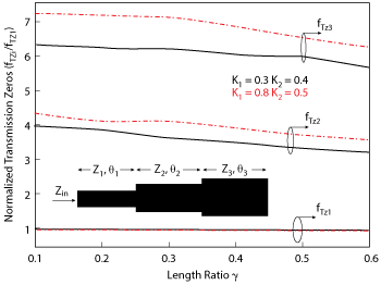
Figure 6 Location of transmission zeroes vs. length ratio γ and different impedance ratios K1 and K2.
References
- H. W. Deng, Y. J. Zhao, Y. Fu, X. J. Zhou and Y. Y. Liu, “Compact and High Selectivity Dual-Mode Dual-Band Microstrip BPF with QWR and SLR,” Microwave and Optical Technology Letters, Vol. 54, No. 12, December 2012, pp. 2702-2705.
- S. Yang, L. Lin, J. Z. Chen, K. Deng and C. H. Liang, “Design of Compact Dual-Band Bandpass Filter Using Dual-Mode Stepped-Impedance Stub Resonators,” Electronics Letters, Vol. 50, No. 8, April 2014, pp. 611-613.
- I. Wolff, “Microstrip Bandpass Filter Using Degenerate Modes of a Microstrip Ring Resonator,” Electronics Letters, Vol. 8, No. 12, June 1972, pp. 302-303.
- K. Chang and L. H. Hsieh, Microwave Ring Circuits and Related Structures, Wiley, New York, 2004.
- S. Luo, L. Zhu and S. Sun, “A Dual-Band Ring-Resonator Bandpass Filter Based on Two Pairs of Degenerate Modes,” IEEE Transactions on Microwave Theory and Techniques, Vol. 58, No. 12, December 2010, pp. 3427-3432.
- S. Luo and L. Zhu, “A Novel Dual-Mode Dual-Band Bandpass Filter Based on a Single Ring Resonator,” IEEE Microwave and Wireless Components Letters, Vol. 19, No. 8, August 2009, pp. 497-499.
- J. X. Chen, T. Y. Yum, J. L. Li and Q. Xue, “Dual-Mode Dual-Band Bandpass Filter Using Stacked-Loop Structure,” IEEE Microwave and Wireless Components Letters, Vol. 16, No. 9, September 2006, pp. 502-504.
- X. Y. Zhang and Q. Xue, “Novel Dual-Mode Dual-Band Filters Using Coplanar-Waveguide-Fed Ring Resonators,” IEEE Transactions on Microwave Theory and Techniques, Vol. 55, No. 10, October 2007, pp. 2183-2190.
- E. E. Djoumessi and K. Wu, “Multilayer Dual-Mode Dual-Bandpass Filter,” IEEE Microwave and Wireless Components Letters, Vol. 19, No. 1, January 2009, pp. 21-23.
- J. W. Baik, L. Zhu and Y. S. Kim, “Dual-Mode Dual-Band Bandpass Filter Using Balun Structure for Single Substrate Configuration,” IEEE Microwave and Wireless Components Letters, Vol. 20, No. 11, November 2010, pp. 613-615.
- T. H. Huang, H. J. Chen, C. S. Chang, L. S. Chen, Y. H. Wang and M. P. Houng, “A Novel Compact Ring Dual-Mode Filter with Adjustable Second-Passband for Dual-Band Applications,” IEEE Microwave and Wireless Components Letters, Vol. 16, No. 6, June 2006, pp. 360-362.
- K. D. Xu, Y. H. Zhang, Y. Fan Y, J. L. W. Li, W. T. Joines and Q. H. Liu, “Planar Dual- and Tri-Band Bandpass Filters Using Single Improved Ring Resonator and Simple Feed Scheme,” Microwave and Optical Technology Letters, Vol. 56, No. 3, March 2014, pp. 574-577.
- J. P. Wang, L. Wang, Y. X. Guo, Y. X. Wang and D. G. Fang, “Miniaturized Dual-Mode Bandpass Filter with Controllable Harmonic Response for Dual-Band Applications,” Journal of Electromagnetic Waves and Applications, Vol. 23, No. 11-12, January 2009, pp. 1525-1533.
- S. J. Sun, T. Su, K. Deng, B. Wu and C. H. Liang, “Shorted-Ended Stepped-Impedance Dual-Resonance Resonator and its Application to Bandpass Filters,” IEEE Transactions on Microwave Theory and Techniques, Vol. 61, No. 9, September 2013, pp. 3209-3215.
- S. Fu, B. Wu, J. Chen, S. J. Sun and C. H Liang, “Novel Second-Order Dual-Mode Dual-Band Filters Using Capacitance Loaded Square Loop Resonator,” IEEE Transactions on Microwave Theory and Techniques, Vol. 60, No. 3, March 2012, pp. 477-483.
- Y. C. Chiou, C. Y. Wu and J. T. Kuo, “New Miniaturized Dual-Mode Dual-Band Ring Resonator Bandpass Filter With Microwave C-Sections,” IEEE Microwave and Wireless Components Letters, Vol. 20, No. 2 , February 2010, pp. 67-69.
- S. Sun, “A Dual-Band Bandpass Filter Using a Single Dual-Mode Ring Resonator,” IEEE Microwave and Wireless Components Letters, Vol. 21, No. 6, June 2011, pp. 298-300.
- S. Sun and L. Zhu, “Wideband Microstrip Ring Resonator Bandpass Filters Under Multiple Resonances,” IEEE Transactions on Microwave Theory and Techniques, Vol. 55, No. 10, October 2007, pp. 2176-2182.
- R. Gomez-Garcia, M. Sanchez-Renedo, B. Jarry, J. Lintignat and B. Barelaud, “A Class of Microwave Transversal Signal-Interference Dual-Passband Planar Filters,” IEEE Transactions on Microwave Theory and Techniques, Vol. 19, No. 3, March 2009, pp. 158-160.
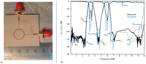
Figure 7 Fabricated dual-band BPF (a), with simulated vs. measured results (b).