
Radio-controlled commercial drones have quickly caught the attention of consumers and entrepreneurs who have created many new and emerging commercial uses. From videography to inspection of crops and infrastructure to delivery of goods, drone technology has become both a pastime for the hobbyist and an essential tool for the business entrepreneur. With many commercial applications and millions of hobbyists flying drones, the commercial sales of drones is expected to reach nearly $10B globally by 2025 according to some reports.
However, with widely publicized incidents, such as a drone landing on the White House garden and near hits with landing planes at airports, the detection, location and mitigation of the possible threats posed by consumer drones presents a new challenge for securing critical or private facilities, infrastructure, public venues and even borders.
There have been about 600 drone incidents that have been recorded by the U.S. Federal Aviation Administration over the previous six months. Civilian-operated UAVs are a problem that is getting worse—on April 17 of this year, a British Airway’s flight making its final approach to London’s Heathrow Airport was reported to have struck a UAV. Two months earlier, another plane that had just departed from Heathrow Airport had a near collision with a UAV.
The UAVs that landed in front of German Chancellor Angela Merkel in September 2013 and on the roof of Japanese Prime Minister Shinzo Abe’s office in April 2015 were flown by protestors trying to prove a point. But in the future, such UAV’s could carry explosives, bio or chemical weapons to perform terrorist attacks. They can also be used to transport illegal items such as drugs, or used to jam radio signals, like GPS or Wi-Fi, interrupting service. Given these concerns, market forecasts for drone detection systems are estimated to grow to about $16B by 2022 according to ASD reports.
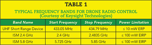
Drone radio controls (RC) typically operate in one of three different parts of the spectrum reserved for remote control devices shown in Table 1. These bands can be very crowded—especially the 2.4 GHz ISM where most commercial Wi-Fi, Bluetooth and IoT (i.e., ZigBee, Z-Wave, LoRa) systems operate. Signals operating in these bands are loosely regulated, using random access rules rather than a controlled time or frequency division access scheme. Thus, there are a large number of signals occurring across the 80 MHz of the 2.4 GHz ISM band. The SRD and 5.8 GHz ISM bands are not as active, but given time they are bound to become the most populated.
Microwave Journal gathered the following three contributed pieces from Rohde & Schwarz, Keysight Technologies and Aaronia AG about RF drone detection and location systems, including the challenges to drone detection, advantages and disadvantages of these systems and some information about their systems. While there are many companies developing these systems, we chose these three leading test & measurement companies to contribute their approaches and views as experts in the area of spectrum monitoring.
RF Drone Detection and Location System
Challenges and Solutions
Darren McCarthy
Rohde & Schwarz
Beaverton, Ore.
Stopping a drone from flying is not a trivial task and no single solution is a panacea. Visual and sound detection can be subject to impaired performance and errors from environmental interference. Radars may not detect drones with a small form factor and Electro/Optical (EO) sensors may not work in adverse weather conditions such as rain or fog. Even RF detection would not be effective alone on a pre-programmed drone using GPS waypoints for guidance. The presence of a radio link is necessary for RF detection. However, a RF detection system is a key trigger point for most of the consumer drone technologies in use and has a distinct advantage of speed of detection versus other technologies.
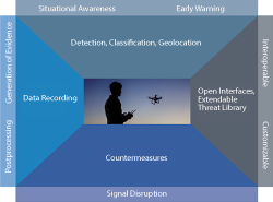
Figure 1 Framework for drone location and detection systems.
To be effective, RF detection systems must provide a high level of sensitivity, give an early warning and not create false alarms. A complete countermeasure system also requires a safe, reliable means of stopping the threat. An RF detection system can be a useful part of the complete workflow for a system that includes other sensor technologies.
One of the critical shortcomings of protection systems has been the integrated workflow between the detection system and the immediate interaction between the detection and countermeasures systems to attain a high level of success.
Figure 1 gives a workflow for consideration and forms the framework for the design challenges of detecting possible threats from drones. In this article, we will focus on the detection and location drones controlled by RF links, and the need for interoperability and customization as technology advances.
Situational Awareness: Detection, Classification and Geolocation
While no universal standard exists for the remote control of drones, the majority of drone technologies are radio controlled and emit an uplink (controller to device) and downlink telemetry or video signal back to the user. The RF detection system has a distinct advantage for the detection of a radio controlled drone—time!
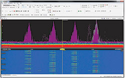
Figure 2 Example of FHSS technology used for a 2.4 GHz drone.
The RF link establishment between the controller and the drone gives the RF detection system a substantial advantage in assessing the threat situation.
While most operate in the unlicensed ISM bands at 2.4 or 5.8 GHz, other frequency bands are also used including 433 MHz and 4.3 GHz. Some of the older frequencies used by radio controlled devices include 27, 35, 40.68 and 72 MHz, which could also offer an extended range of control to several kilometers. The ability to track and detect possible devices requires a broadband antenna and receiver system capable of monitoring all the critical bands of interest on the hunt for possible threats. Further, since these ISM bands and devices operate with very low power (~100 mW) and in the presence of other legitimate RF uses with similar technologies, like WLAN, the high sensitivity to see signals at distance ranges and discern legitimate versus unauthorized threats requires operation expertise in signal analysis and automatic detection is required.
Figure 2 shows an example of a drone using FHSS technology in the 2.4 GHz ISM band. In the upper display, the RF spectrum shows the signal persistency on a temperature scale which is the presence of a signal over a period of time that is channelized into four frequency channels. The lower display shows the spectrogram, or waterfall, of the same signal over time with the color scale representing amplitude. A detailed analysis of this signal will show that this signal is hopping between the different RF spectrum channels with a specific burst duration, channel sequence or hopping pattern, and at a specific hopping rate (~ 100 hops/s). From this display, the clean spectrum and lack of other signals makes it easy to recognize the pattern of this FHSS drone, similar to what one might find in a lab or controlled environment.
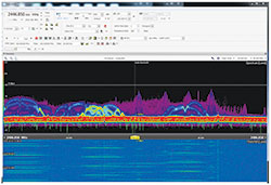
Figure 3 A drone signal in the presence of normal traffic from Wireless LAN.
Consider the environment represented in Figure 3. This now becomes a little less obvious to a system operator when in the typical environment of crowded ISM band technologies. The presence of multiple WLAN access points and user terminals, Bluetooth technologies and IoT devices, can all be present in the same spectrum and the FHSS drone can be lost in the view. Also, keep in mind that some drones utilize WLAN signals for control or downlink video, so deeper inspection and decoding of WLAN signals is warranted to detect motion.
To reliably detect a drone signal, automatic classification is essential. A human operator cannot be expected to understand and assess all signals in all frequency bands in a timely manner. A simple threshold-based RF alarm signal, available on many basic spectrum monitoring systems, can lead to false alarms whenever a signal threshold is detected. The automatic classification system must recognize the expected environment and be able to look for the transmission system for classifying the signature, of an expected threat from a library of known drone signals. Time is the biggest advantage of an RF detection system during the link establishment, and this advantage must be used to improve situational awareness.
The multi-drone environment must also be considered. There may be situations where a “friendly” drone (white list) would be used for perimeter monitoring, police investigation or crowd observation. The individual identification of known “friendly” signals must be assessed against the environment. This presents the opportunity where a drone threat (black list) may coexist with a white list asset. This leads to the question of how many threats are expected in an environment.
There is a complex challenge to rapidly classifying signals in a multi-threat environment (see Figure 4), especially considering the complexity of separating the signatures of multiple commercial drones using FHSS, WLAN and Bluetooth technologies operating on the same frequency band, and others that might operate on other frequency bands. Not only is this a challenge during the signal classification process, but it must also be noted that not all direction finding technology perform geolocation equally in a multi-signal environment. This is especially true with direction finding technologies that are not able to distinguish multiple signals at the same time on the same frequency, but emanating from different angles of arrival.
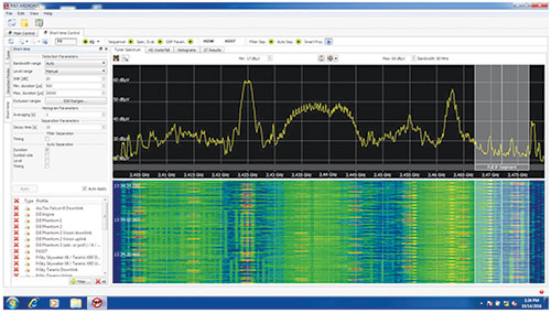
Figure 4 A multi-threat environment with multiple drones (uplink and downlink) identified (lower left).
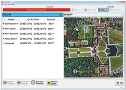
Figure 5 Example Geo-location of drone threats and a “friendly” drone Interoperability and Future-Proof.
The selection of direction finding technologies must also consider the ability of the system to geolocate threats that are occurring at the same time and on the same frequencies, as well as the ability to operate over the entire expected operational band. It is important that behind the technology of the system, these threats can be presented to the user in a clear manner for them to be able to act upon the threat. Figure 5 gives an example of four drones being detected at the same time and the angle of arrival of each of the threats and the friendly police drone.
RF detection systems play an essential part of a drone defense system; however, there are drone technologies that can operate based on a GPS, or other GNSS technologies, waypoint system that do not emit an RF signature. In this case, sole reliance on an RF detection system would be inadequate protection for high-valued targets.
The complete solution must consider other technologies that can work in concert to complement the advantages and overcome the disadvantages of sole technologies reliance. Therefore, an open system interface that can enable any of these other technologies to “tip” the defensive system is important. Alarms or tipping of other systems should also consider visual or acoustic methods as well as text messaging (SMS) to predefined groups of mobile phones or as an XML message via an IP network.
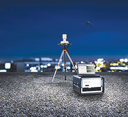
Figure 6 Rohde & Schwarz’s R&S®ARDRONIS-D radio monitoring solution combines detection, classification and geolocation in a single, portable, highly reliable system.
As drone technologies continue to advance, new RF interfaces continue to be incorporated into these commercial devices. It is important for the detection system to have a scalable approach to extend and incorporate new RF signatures as they become available. A database is only good against known threats. Continued vigilance against the new advances in RF interfaces is essential, and the ability to augment the protection system to the latest threats remains imperative.
An example system is the R&S® ARDRONIS technology (see Figure 6), which has already demonstrated itself as acceptable for the highest levels of security. At the G7 Economic Summit held in Elmau Castle, Germany and again during U.S. President Barack Obama’s visit to the Hanover Trade Fair in 2016, the system’s underlying technologies were used to secure the sites from unauthorized, remote controlled drones.
The R&S® ARDRONIS automatic radio-controlled drone classification solution is a comprehensive solution with specialized capabilities for detecting, classifying, geolocating, recording and disrupting the remote control link to a drone. The solution is optimized for countering the threats arising from radio controlled (RC) drones. Through successful trials, deployments with key customers, involvement in protecting various important and public events as well as VIP persons, R&S® ARDRONIS has proven to be an effective technical approach.
R&S® ARDRONIS is a reliable approach to effectively detect and monitor drone activity and achieve early warning capability. It meets the challenge of identifying the direction of operators by finding the direction of active remote controls and drones. Effective countermeasures can be deployed in time to counter and prevent a radio controlled drone from entering a defined area by disrupting the radio communications link. The capabilities and key functionalities of R&S® ARDRONIS include classification, geolocation and countermeasures for threats imposed by radio-controlled drones.
Summary
There are many considerations to the challenges of the potential threats presented by drones. The widespread use of commercially available drones heeds warning to an increased need for vigilance these threats may possess for potential high-valued targets and critical sites.
The depth of the solution obviously needs to be weighed against the possibilities of the threat and the potential of the threat to change over time. RF detection systems have a distinct advantage of reaction time along with a high probability of use. The actions and workflow of how to respond to a threat must play into how components of a defensive system can complement their actions for a complete solution.
The careful consideration of the type of RF detection system must also consider the need to be able to sift through the myriad of RF signals in a dense spectrum environment and simultaneously reduce the false alarm rate. One needs to be able to tell the difference between a Wi-Fi signal someone turns on for their own personal hotspot and the Wi-Fi signal of a drone. As new signals appear and technology advances, skilled users should be able to define their own threats to be included in the classification database, or a service level agreement to renew and keep the database current with technology should be made available.
Geolocation technology needs to be carefully considered and technology assessment should be performed against an anticipated scenario. Choosing a direction finding technology that is blind to a multi-threat environment could have disastrous consequences.
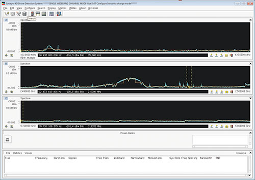
Figure 7 Keysight Surveyor 4D Drone Detection System display
RF Techniques for Detection, Classification and Location
of Commercial Drones
I.C. Tillman
Keysight Technologies
Santa Rosa, Calif.
An effective drone detection system monitors all three of the bands, 433 MHz SRD and 2.4 or 5.8 GHz ISM, while skipping over the vast spectrum in between (see Figure 7). This results in a fast and efficient way to focus only on the parts of the spectrum where drones are known to operate. Each band is configured with different resolution bandwidths (RBW) and trace averaging schemes based on the typical bandwidths and features of the drone control signals. For example, drone control signals found in the SRD band (400 MHz) are usually only tens of kHz wide and have unique spectral shapes. For that reason, narrow RBW (i.e., less than 3 kHz) is appropriate in this band. The signals of interest in the 2.4 and 5.8 GHz ISM bands tend to be 1 to 2 MHz wide; therefore, a wider RBW (i.e., 20 kHz) is beneficial. The wider RBW allows for faster processing of the spectrum and higher probability of intercepting a drone RC transmission.
Isolating the Right Signals
A robust method for automatically detecting energy relative to the “noise” floor that can function across all three bands is needed. A noise riding technique is used that was originally developed as part of a signals development system for the HF Band (2 to 32 MHz) at Keysight. The algorithm has variables related to the margin (amplitude offset), segmentation (frequency granularity) and smoothing (a running average). By properly setting these values, the auto-threshold can “ride” up and down active Wi-Fi channels but still properly respond to and isolate drone control signals from other transmitters legally authorized to operate.
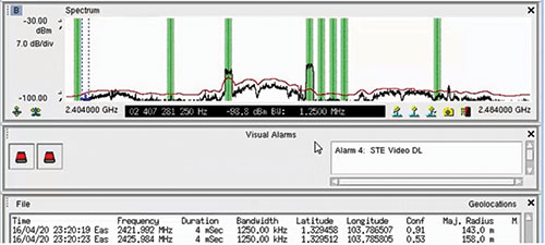
Figure 8 Operation of the Auto Threshold algorithm in ISM band.
Figure 8 shows how the algorithm works. The vertical green lines show detections of frequencies with the drone RC. The red line represents the noise riding threshold which is “riding” on top of the Wi-Fi signals but detecting the control signals. The next challenge is to discriminate one type of drone control signal from another. The noise riding threshold helps by rejecting ambient Wi-Fi signals, treating them somewhat like a noise floor. However, there are other signals that may resemble the drone RF of interest. But what if more than one RC is operating, how can they be differentiated?
Differentiating Drone Control Types
This challenge can be addressed by spectral shape correlation. This isolation technique uses a spectral correlation line consisting of points horizontally separated by the frequency bin spacing (a value related to the RBW by the FFT filter shape factor). The points are vertically positioned based on the unique amplitude features of the transmission. The number of points in the detector is based on the signal bandwidth, or the bandwidth of the exploitable feature of the signal. Basically, these are matched filters used to evaluate every set of frequency bins in the sweep for a match within a defined tolerance (expressed in percent or dB). Correlation lines for specific signals are built from recordings and validated in several steps prior to being put into use.
Each make of radio controller employs a slightly different scheme to communicate with the drone. It is these differences that can be exploited by a spectral shape correlator. Figure 9 shows the signature of one type of controller.
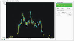
Figure 9 Spectral Shape correlator for a specific drone signature.
A Keysight Signal Surveyor 4D feature called “Universal Signal Detector” or USD is used, which has a spectral shape correlator referred to as a wideband detector. This feature enables the user to apply signal discriminators designed to recognize various drone controllers with minimal false positive results. The USD “detector” applies three other elements that work together, or independently, to distinguish signals of different types. Once again, this feature was originally developed for use in the HF spectrum where signals often have unique spectral signatures that can be exploited. The other elements used by the USD feature are:
- Frequency plan, which can include a frequency band with or without channelization and individual frequencies,
- Bandwidth filter, with a tolerance expressed in percent,
- Narrowband confirmation of the modulation and symbol rates, not typically required for drone RC discrimination.
Locating the Radio Controller Using Time Difference of Arrival (TDOA)
Locating transmissions in the ISM band can be a challenge for many reasons. Ambient signal energy is literally everywhere due to the overlap of the Wi-Fi channels, Bluetooth activity and an increasing number of IoT signals presenting in this 80 MHz wide band (see Figure 10). The signals are short in duration, frequency hopping (over most of the band) and relatively low power. Affordable network-enabled sensors can be distributed around an area and used to both detect and locate these signals. A distributed detection system is beneficial in expanding the coverage area. Since drone control signals will most likely be operated from the ground, at an elevation of about 1.5 meters, the detection range of any monitoring system will be less than for an elevated transmitter. Additionally, since the signals are moderately wide bandwidth (1 to 2 MHz), the power spectral density is less than that of, for example, a PMR radio (12.5 to 25 kHz). Thus, the propagation distance is less.
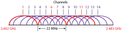
Figure 10 Overlap of Wi-Fi channels in 2.4 GHz ISM band.
Given these conditions, for successful geolocation using TDOA, the signals must be isolated both in frequency and in time. For TDOA to work, the right “snippet” of synchronous IQ data from each sensor must be collected and correlated at a common host computer. The bigger challenge is isolating the correct samples of IQ (i.e., that contains the RC signal) from all sensors. For this to be feasible, each sensor must have precisely time-stamped IQ memory to get the right pulse. Given that drones can occur in any one of three bands, it is assumed the receiver is sweeping across all bands. This means the IQ from each frequency segment, corresponding to the tuner IF bandwidth, must be properly time-stamped and indexed in the sensor memory. When an RC signal is detected, the system must communicate the refined time to each sensor and request that data specifically from the memory. The host PC can then correlate the IQ data between all sensor pairs and estimate the position. Figure 11 shows an example of how this measurement looks.
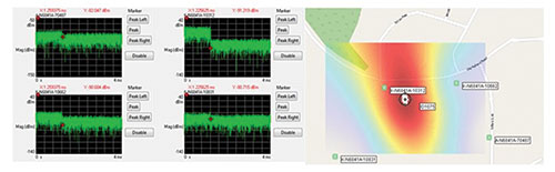
Figure 11 Drone RC burst capture and TDOA geolocation in the Keysight N6854A Geolocation Server Software.
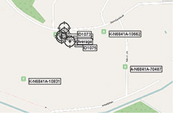
Figure 12 Clustering of TDOA results around RC.
The four sensors have synchronously isolated the RC signal from the 2.4 GHz ISM band and successfully isolated, in time, the 1.2 ms burst. The host computer was able to correlate the IQ time series data to successfully estimate the location of the controller. This measurement was taken during field testing, so the time record was 3x longer than required. This “lookback” method of isolating short duration signals has proven effective for locating drone RCs.
Another challenge presented by the ISM band is co-channel interference, which presents issues for any technique used for emitter location. When using traditional direction finders (i.e., angle of arrival techniques), strong co-channel signals present during signal acquisition can produce angular errors or a result based on the interferer rather than the intended signal. Angular errors can be difficult to overcome whether they are produced by reflections or co-channel interference, both of which dominate the landscape especially considering the ISM band in urban environments. TDOA algorithms usually base the result on the strongest correlation. This is where isolation of the RC signal burst in time is critical. By triggering the geolocation measurement window on the exact RC signature, the likelihood of a strong correlation is very high. Since the RC is hopping, several TDOA measurements will be completed in a short time increasing further the chance of a strong clustering of the geolocation results (see Figure 12). A direction finding system employing multi-channel correlative techniques could overcome this situation, but at a far higher cost.
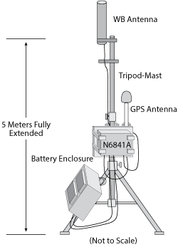
Figure 13 Keysight Surveyor 4D Drone Detection System.
Techniques developed to detect, isolate and classify signals in the HF band can be effective against signals in the ISM band. While the HF band has a poorly behaved noise floor that varies based on environmental conditions, the ISM band also has a very active ambient signal floor consisting of a variety of overlapped wideband and frequency agile narrowband activity. This signal activity behaves somewhat like the HF band except at a much higher speed of variation. An automated noise riding threshold combined with spectral shape correlation detection makes for an effective, low cost way to detect and isolate specific signal energy. Once detected, TDOA methods using sensor memory can effectively isolate the pulsed signal data for cross-correlation to estimate the RF controller location. Such systems can be implemented with low-cost, synchronous sensor networks.
An example system is the Keysight Surveyor 4D System (see Figure 13), which is effective at detecting, classifying and locating drone controllers operating within a 1 km range. Detection range can be extended by additional elevation on the system that extends line of sight. The enabling technology is in the Surveyor 4D’s high-speed multiband search mode and the Universal Signal Detection (USD) wideband detector. The system can create detectors as new drone systems are introduced. This provides the user with the ability to update the library of drone detectors as new control units and drone products enter the market.
Keysight offers a modeling and simulation tool for planning RF Sensor installations called SPOT (Sensor Planning and Optimization Tool). With this tool, detection sites can be planned to provide the best possible coverage for critical infrastructure or event locations. With the deployment of four or more sensors, emitter location by Time Difference of Arrival (TDOA) is possible.
Detection of UAV´s Based
on Their RF Emissions
Aaronia AG
Strickscheid, Germany
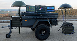
Figure 14 Aaronia’s Drone Detector System.
A final example is Aaronia’s Drone Detector, a product that exploits the RF radiation emitted by the UAV’s onboard systems and by the operator’s control unit (see Figure 14). Aaronia recognized the need for a reliable method to detect tiny airborne intruders. Following a four-year development program, it launched the product. Real-time RF signal detection, combined with what the company terms “pattern triggering,” provides rapid warning of any UAV or UAV control unit that is operating within the area being monitored.
Military communications links often exploit techniques such as frequency agility in order to reduce the probability of interception, but the designers of UAVs are selling an inexpensive commercial products. As a result, UAV communications links are low-cost, unsophisticated sub-systems that have few clandestine qualities. Since the Drone Detector has more sophisticated receiver facilities than those of the UAV and its control unit, it has a longer range than the UAV operator.
Two types of 3D direction finding antennas are offered by the Drone Detector—the IsoLOG 3D 80 and IsoLOG 3D 160. These have eight sectors with 16 antennas, and 16 sectors with 32 antennas, respectively. Both cover from 680 MHz to 6 GHz, and extenders are available should LF, MF, HF and VLF (9 kHz to 680 MHz) and 6 to 20 GHz coverage be required.
These antennas are teamed with either an XFR V5 PRO (used for portable installations) or an RF Command Centre (for stationary use). Both cover frequencies from 9 kHz to 20 GHz, so include the frequencies commonly used for UAV control and video links—typically 433, 900, 915 MHz and 1.3, 2.4, 5.8 GHz.
Locating the UAV and its Control Unit
Using these basic components, the user can opt for systems of varying complexity. The simplest consists of a single IsoLOG 3D antenna and a stationary or mobile spectrum analyzer. This is sufficient for surveillance of an area with up to 4 to 5 km radius. If a fully mobile solution is required, the system can be installed on a vehicle and operated from battery power. Its antennas are resistant to the effects of salt water splashes or spray, allowing deployment on a boat.
Once a signal has been detected, its approximate bearing will be shown to an accuracy of 2 to 3 degrees, which depends on which model of antenna is being used. With the standard IsoLOG 3D 80, the bearing accuracy will be at least within the 4 to 6 degrees coverage of a single antenna sector.
When larger areas must be covered, several antennas and spectrum analyzers can be connected to a single centralized PC which manages these simultaneously. The larger the area to be covered, the greater the number of antennas and analyzers that must be deployed. Any threat signal is likely to be received by several antennas, so the results can be triangulated to provide detailed and accurate information on the location of the UAV and/or its operator.
The system has no limitation in detection range; usually the detection range is the same as the usable distance from the operator to the drone (or better), so it always depends on the transmitter power of the drone/operator. Depending on the drone type, it could be several kilometers/miles without a problem (e.g. approximately 5 km for a DJI Phantom 4).
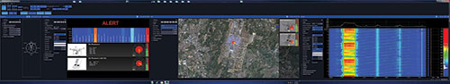
Figure 15 Identification of multiple drones.
Since the system is designed to recognize the RF signals associated with UAVs by observing their frequency and other characteristics, it will not provide false alarms when faced with other types of RF signals. When faced with several UAVs, the system can detect these, even if the drones are the same or different types (see Figure 15).
The average time needed for detection of a UAV is between 10 microseconds and 500 milliseconds. It depends on factors such as the complexity of the deployed system and the number of antenna arrays being used. While a clear line of sight between the antennas and the UAV or its operator gives the best results, the system can detect RF signals whose source is obscured by trees, bushes or a crowd of people. The system is passive, emitting no signals of its own that could interfere with the normal operation of nearby assets, such as airports, or give the UAV operator warning of its presence. System performance is unaffected by darkness or poor weather—if meteorological conditions allow UAVs to fly, they can be detected.
The Aaronia system has some unique features like 24/7 recording and playback. Further it can be equipped with multi-receivers allowing real-time measurement of each individual frequency band (e.g. 2.4 and 5.8 GHz, 434 and 868 MHz) without the need to switch between bands.
Summary
While drones will enable many new exciting applications in commercial markets, they also represent a potential threat to public safety. Since they are small and agile, they can access most protected areas and are difficult to detect and prevent them from entering these areas. However, new drone detection and location systems, mostly based on RF technologies, are rapidly evolving to protect the public from these threats. Many RF test and measurement companies are uniquely positioned to leverage their spectrum monitoring capabilities to field systems in this area.