
Modern radar systems require advanced test and verification techniques to ensure that these systems can operate under complex and cluttered communication environments, and that their performance specifications are fully met and further characterized. When engineers configure an automated test setup for radar systems, some of the most important instruments used to evaluate the system are an RF/microwave signal generator and a spectrum analyzer. A signal generator can be used as a test stimulus to simulate the operational environment precisely, and a basic function generator can be used to drive the pulse, AM and FM circuitry of an analog signal generator. In the receiver, the weak signals received by the antenna can be detected and amplified by a spectrum analyzer with high dynamic range and low phase noise.
With the recent advancements in radar technology, such as active electronically scanned arrays (AESA) and multifunction systems, radar test requirements are becoming increasingly challenging. This article will describe these challenges and the test requirements of a modern automated test equipment (ATE) system that is capable of next-generation radar test.
TESTING MODERN RADAR SYSTEMS
Modern radar systems must be able to resolve targets in complex signal environments, requiring a lower distortion receiver than what was historically used. To meet the most stringent receiver specifications, testing requires a source that can generate a signal with low phase noise and excellent spurious and harmonic performance. Because of the difficulties involved in the direct conversion from the digital domain to microwave frequencies, or vice versa, it is common to use more than one local oscillator (LO) for multi-stage conversion. When using multiple LOs, they must all be synchronized and phase locked with each other, as tightly and quickly as possible. The faster they can be phase locked and synchronized at the desired frequency, the faster the overall test and measurement time. Synchronization is of particular concern in an AESA radar, as it involves thousands of receivers connected to the antennas, and each of the receivers needs to be synchronized.
As mentioned, testing radar receivers can use signal generators for a variety of test signals, ranging from pulsed CW to chirps using frequency modulation and sweep. Commonly, radars use pulsed RF/microwave signals for testing, and the characteristics of the pulse largely determine the performance and capabilities of the system. For instance, pulse power determines the range of the target and the pulse width ascertains the spatial resolution of the target. In radar test and verification, a signal generator can be used as a source for LO substitution, where the low phase noise and high spectral purity of the signal generator allow for a higher dynamic range and improved sensitivity of the measurement receiver.
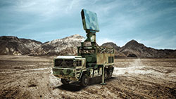
Figure 1 Giraffe 4A AESA radar.
The advent of AESA multifunction radar systems has led to an unprecedented enhancement in radar performance, reliability and scanning speed. A typical AESA architecture involves thousands of transmit/receive (T/R) modules, each with an antenna. Adding to the complexity of the design, the precise phase and amplitude alignment of each T/R module challenges radar testing and verification.
GIRAFFE 4A AESA RADAR
AESA radars have significantly evolved over the past three decades, with continuous advancements in signal processing and RF/microwave technologies such as GaN power amplifiers, monolithic microwave integrated circuits (MMIC), millimeter wave integrated circuits—all leading to reduced cost of the T/R modules. Unlike conventional mechanically steered array (MSA) or passive electronically steered array (PESA) radars, AESA radars allow digital and independent control of the module transmit/receive gain and phase. This capability provides a significant advantage in beamforming and the beam steering agility of the radar. AESA radars are much more reliable than the traditional radar, mostly because the thousands of independent T/R modules—instead of a single channel—allow the radar to sustain some level of failure without disabling the entire system. The modular approach of the AESA provides a seamless ability to replace the T/R modules with more advanced elements as they become available, leading to notable improvements in performance.
One example of an AESA multifunction radar is Saab’s Giraffe 4A radar (see Figure 1). The Giraffe 4A is a software-defined radar with multifunction operational flexibility; the operator can adaptively switch between different modes of operations by dynamically modifying signal processing tasks and waveforms. The Giraffe 4A is a great case study to highlight the requirements for the modularized radar ATE system needed to address the radar test requirements. The Giraffe 4A radar is composed of three functional elements: the exciter, receiver and antenna. The major requirements of testing and characterizing each of these elements are defined below:

Figure 2 Battlefield simulator consisting of an NI PXIe-5663 VSA for performing RF measurements, a PXIe-5114 digitizer acting as an oscilloscope and a PXIe-5664R vector signal transceiver for real-time scenario simulation using an onboard user-programmable FPGA.
Exciter: The primary role of an exciter is to generate the internal LOs for the receivers and a carrier signal for the transmitters. The generated signals must be stable, low in phase noise and spurious content and fast when switching frequencies. Low spurious content and harmonics make a clean transmitted signal. With a clean LO signal fed to the receiver, it is much easier for the receiver to detect the signal of interest in a cluttered environment.
Receiver: The function of a receiver is to extract the weak reflected signals from the antenna, amplify them without adding noise or distortion and pass them to the processor for pulse decompression/signal processing. The receiver must have a low noise factor and high resistance to interfering signals. Receiver noise (precisely, the sensitivity) limits the range of the radar. Low phase noise is critical to detect and track small changes in the targets. The receiver must also have a high dynamic range to prevent large clutter signals from saturating the system.
Antenna: The antenna receives energy from an electromagnetic (EM) field and radiates EM waves produced by the exciter. The AESA antenna consists of radiating elements and an antenna structure, T/R modules and associated control circuitry, RF beamformers, DC power distribution and a beam steering controller. The antenna must have a precise main lobe (the region around the direction of maximum radiation), low side lobes to minimize radiation in undesired directions and rapid steering of the main lobe for beamforming.
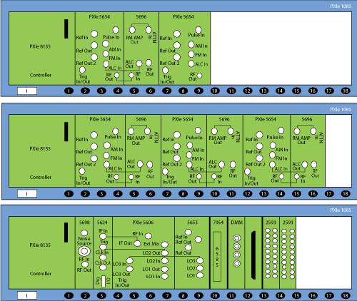
Figure 3 The three PXIe chassis configuration for the Giraffe 4A radar.

Figure 4 BTE building blocks provide the resources for the UUT tests.
MODULARIZED RADAR ATE SYSTEM
To test and characterize the performance of the sub-modules of the Giraffe 4A radar, engineers at Saab decided to use the National Instruments (NI) PXIe-5668, a multi-stage, superheterodyne, 26.5 GHz vector signal analyzer (VSA). Along with low spurious and harmonic content, NI’s VSA offered the desired dynamic range with a reasonable sweep time across the entire instantaneous bandwidth of 765 MHz. The modular form factor of the PXIe-5668R was well-suited to the standard of the Saab radar test bench. To meet cost and size constraints, Saab’s test engineers designed an in-house phase noise measurement system using NI PXIe modular instruments. The phase noise measurement splits the acquired signal into two channels, down-converts each into baseband analog waveforms using LO signals and feeds these analog waveforms to the digitizers for cross-correlation. This system also uses other PXIe instruments, such as digital I/O, driver and switch modules to control the down-converters, multipliers, dividers and switching circuits. The entire phase noise measurement system is controlled using LabVIEW. For antenna testing, the test engineers built an indoor test range and simulated the battlefield scenario using an NI PXIe-based scenario simulator, with remote access through a LabVIEW-based application (see Figure 2).
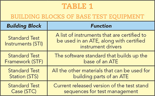
Figure 5 VPC interface used to select resources from the BTE.
The modular nature of the test setups, using LabVIEW, allowed for integration of many instruments into one state-of-the-art radar ATE system. This ATE system contains three PXIe chassis (see Figure 3) equipped with five PXIe-5654 RF signal generators, four PXIe-5696 amplitude extension modules and a PXIe-5668R VSA with a low noise microwave front end. It also contains an NI FPGA board with a low voltage differential signaling (LVDS) module, used mainly as a controller for sending and receiving commands to the units under test (UUT). Included in the system is an NI relay driver module to control the switching in the ATE fixture, a microwave PXI switch module to route signals in the ATE, an NI PXI digital multimeter (DMM) and PXI multiplexer modules to route low frequency signals. In addition to the three PXI chassis, the ATE system has two 19-in racks that hold a computer, power distribution circuit, power supplies and Virginia Panel Corporation (VPC) interface, with room to add more instrument signal paths, depending on UUT requirements.
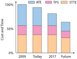
Figure 6 Reduction in ATE cost and time for testing new radar systems.
Figure 4 shows the general building blocks of the base test equipment (BTE) in an ATE, and their functions are listed in Table 1. The VPC interface is used as a mass interconnect between the test instruments and the UUTs, allowing the user to connect different fixtures, such as special type test equipment (STTE) designed and built according to customer specifications (see Figure 5).
BENEFITS OF PLATFORM-BASED RADAR ATE
Architecting a modularized radar ATE system involves addressing several key requirements determined by the UUT, as seen in the Giraffe 4A AESA radar example. Building a PXI-based modular ATE system offers advantages over conventional approaches for radar testing, including cost, time and standardization.
Time and Cost Savings
With the continuous evolution of and rising demand for new test requirements for modern radars, the BTE libraries are adding more functionality and support for verified drivers and documentation of the instruments in the ATEs. Traditional ATE systems require expensive retooling on the test floor, as generations of systems become obsolete or are unable to meet new test requirements. The nature of the open PXI architecture helps ensure an efficient use of resources and optimal reuse of products and engineering. Figure 6 shows the reduction in engineering effort, reflected in cost and time, to meet the demands of new radar test requirements.
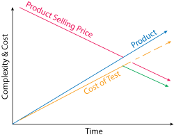
Figure 7 Complexity and cost vs. time for high-tech products.
As illustrated in Figure 7, products are becoming more complex, and the cost of development and testing is increasing with the complexity. However, the average selling price is declining, driving the demand to lower test cost. For the system to remain profitable, the cost of test must be reduced at or faster than the reduction in manufacturing price. By adopting a PXIe platform-based approach, Saab reduced test cost and achieved improved performance, scalability and test speed with reduced footprint and power consumption.
ATE Standardization
The process of standardizing a radar ATE system using a platform-based approach has the advantage of interchangeability. As new technology becomes available, it can seamlessly upgrade older test systems, delaying or eliminating obsolescence. The PXI platform-based radar ATE has interoperable components that work in combination through a common programming and operating environment, such as LabVIEW. Over time, the personnel required for utilizing, operating and maintaining these systems do not need specialized training, which leads to cost saving.
Figure 8 illustrates the correlation between test strategy and product life cycles. The “Products” curve in the figure indicates the number of products that will pass the test during a production lifetime and “Test Systems” reflects the total number of ATEs. Blue indicates test software, green indicates test hardware and yellow indicates instruments from the list of BTE described in Table 1. The plot shows that the capacity of the production line can be more than doubled with an additional ATE fixture. Standardizing on a PXIe platform-based approach for ATE establishes a long-lasting test strategy that correlates with the product’s life cycle.

Figure 8 Correlation between test strategy and product life cycles.
SUMMARY
The radar design and test engineer must carefully assess the specifications of test instruments when building a radar test system and make choices to maximize the return on the investment. With recent advancements in multifunction radars, such as AESAs, test systems are becoming more complex and expensive, driving the need for a state-of-the-art, modularized radar test system that meets the testing requirements while reducing the cost of test. By standardizing the radar ATE framework on the NI PXI platform-based approach, Saab was able to significantly reduce the engineering resources, in cost and time, required to meet the increasingly complex test requirements of advanced AESA radars.