
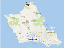
Figure 1 The Opana radar site was located on the northern tip of Oahu. Source: Google Maps.
On Sunday morning, December 7, 1941, U.S. Privates Joseph L. Lockard and George Elliot were ending their shift operating the new, state-of-the-art SCR-270 radar (Set Complete Radio, no. 270) at the Opana radar site on the island of Oahu in Hawaii (see Figure 1). They were scheduled to shut off the radar at 7:00 a.m., but Elliott wanted to keep going. He was still learning to operate the oscilloscope and needed more practice. They had time, as the truck picking them up had not arrived. Lockard, who had more experience with the system, was training the eager Elliot.
At 7:02 a.m., the men were startled by the image on the screen. Lockard said he saw an extremely large signal on the radar. “It was the largest group I had ever seen on the oscilloscope. It looked, as I said, like a main pulse and that is why I was confused, at first, as to whether it was a flight or not. I had never seen one... it produced the largest echo on the scope that I had ever seen.”1 They had detected Japanese planes, 132 miles out from the station, on their approach to attack Pearl Harbor.
After some discussion and cross checks to determine whether the blip was a malfunction, Elliott decided to report what they were seeing. Calling the switchboard, the operator told him that all of the plotters had just left for breakfast. A central team of plotters manually charted the radar echoes on a table to show the location of objects called in by the various radar sites. Around 7:20 a.m., Lieutenant Kermit Tyler returned Elliott’s call and listened to his observation. Tyler knew that B-17 bombers from the west coast of the U.S. typically arrived around 8:00 a.m. He had heard the local radio station on the air before 7:00 a.m., which pilots had told him was a sure sign that the B-17s were coming, as they used the radio signal for homing.1 He assumed that explained the blip Elliott and Lockard were observing and summarized his assessment with the infamous statement, “Well, don’t worry about it.”2
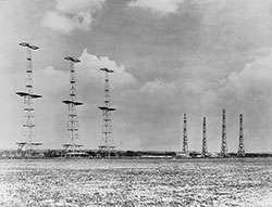
Figure 2 The Chain Home was the first British radar system, used during World War II to warn of approaching German aircraft. Source: Wikimedia Commons.
Elliott and Lockard continued to track the unidentified planes for more than 30 minutes, until the planes became lost in the ground clutter. Leaving the site and coming down the hill for breakfast, they soon learned that Pearl Harbor was under attack. Inadvertently, the blip on the oscilloscope that had confused them was the first wartime use—and validation—of radar technology by the U.S. military, a technology that played a major role during the rest of World War II.
GLOBAL DEVELOPMENT OF MILITARY RADAR
Throughout the 1930s, political unease and military uncertainty led several European countries, the United States and Japan to independently investigate the use of radio echoes for aircraft detection. This research led several countries to develop some form of operational radar equipment that was fielded by the start of the war.
Britain began radar research for aircraft detection in 1935. By September 1938, the first radar system, the Chain Home (see Figure 2), was operating around the clock and remained operational throughout the war, offering vital early warning of the heavy German aerial bombardment. The Chain Home radars, which were deployed under the direction of the inventor of British radar, Sir Robert Watson-Watt, made use of “available, working technology” and operated in the shortwave region, around 30 MHz.3 The Germans pushed the development of radar in advance of the war, installing a radar on a naval pocket battleship as early as 1936.3 Except for some radars that operated at 375 and 560 MHz, all of the successful radar systems developed prior to the start of World War II were in the VHF band, below about 200 MHz.3 However, VHF radar systems suffered performance issues due to broad beamwidths that limited accuracy and resolution, and they were susceptible to echoes from the ground or other clutter. In the 1930s, the Soviet Union also researched military radar, and by the time the German offensive on the country was launched in June 1941, the Soviets had developed several types of radar including a production aircraft detection system that operated at 75 MHz.3
These early developers were aware that higher frequency operation was desirable, particularly since narrow beamwidths could be achieved without excessively large antennas. Using microwave frequencies became feasible in 1939, when the cavity magnetron oscillator was invented by British physicists at the University of Birmingham. The concept of the magnetron was shared with the United States in 1940, which became the basis for work by the Massachusetts Institute of Technology (MIT) Radiation Laboratory in Cambridge. More than 100 different radar systems were developed by the laboratory’s program during its five years of existence (1940-1945). The microwave magnetron made many radar advances possible during World War II.
U.S. RADAR DEVELOPMENT
The U.S. Signal Corps had been experimenting with radar as early as the late 1920s. In the 1930s, the U.S. made a concerted effort to develop radar technology for military use. In August 1935, pulse radar testing began at Fort Monmouth and Fort Hancock, both in New Jersey, and produced positive results using a transmitter on a rooftop at Fort Monmouth and two receivers at Fort Hancock and Monmouth Beach, New Jersey.4 By December 1936, the U.S Signal Corps had developed a working prototype and by May 1937 had demonstrated the system detecting a bomber at night.4 The nighttime test was particularly impressive, because the bomber was off course. Intended to fly in a specific area, so the radar could detect it, the pilot could not find the correct coordinates. The radar located the plane by searching a wider area. After the initial development and testing, the radar project was moved from Fort Monmouth to Fort Hancock, because the latter was a secure facility. From the summer of 1937 to the summer of 1938, the radar group at Fort Hancock developed and tested the SCR-268, the first radar system that utilized both infrared and radio detection. The thermal system was not developed further, after the program determined it was not needed. In parallel with the SCR-268, longer range versions of the system were developed: the SCR-270 mobile and SCR-271 fixed verions. Although the SCR-268 was deployed at the Panama Canal before the SCR-270 was fielded in Hawaii, it was not the first to be used in wartime.
The U.S. military established an Aircraft Warning Service (AWS) to defend American territory in December 1939. The AWS deployed six mobile radar early warning sites on Oahu: Kawaiola, Wainaae, Kaaawa, Koko Head, Schofield Barracks and Fort Shafter. In November 1941, the SCR-270 system at the Schofield Barracks was moved to the Opana site, 532 feet above sea level with an unobstructed view of the Pacific Ocean. The month prior, a joint exercise performed by the Army and Navy on Oahu tested the readiness of the early warning system. Carrier-based aircraft simulated an attack during the predawn hours, and three Army SCR-270 radar units were able to detect the aircraft 80 miles out.4 The exercise was successful, showing the technology worked, but not guaranteeing that future radar returns would be interpreted correctly.
After the Japanese attack, the British Royal Air Force (RAF) sent Watson-Watt to advise the U.S. military on air defense technology. He pointed out the general lack of understanding of the capabilities of radar at all levels of command. Radar was thought of as a new gadget “producing snap observations on targets which may or may not be aircraft.”5 The SCR-270 had operated as designed, but the data it generated was not handled properly. There were several failures: The privates reporting their observations did not say that the display appeared to be a formation of more than 50 planes, which may have changed the reaction of Lieutenant Tyler, who received the report. Tyler was too quick to dismiss the information, instead of investigating further and passing the report up the chain of command. However, even if the early warning had been effectively communicated and recognized, historians doubt it would have made much difference to the outcome of the surprise attack, since the Japanese sent such an overwhelming force.
THE SCR-270 RADAR
The SCR-270 radar operated at 106 MHz, using a pulse width from 10 to 25 µs and a pulse repetition frequency of 621 Hz. With a wavelength of about nine feet, the SRC-270 was comparable to the contemporary Chain Home system being developed in England, but not as high in frequency as the microwave systems developed in Germany at the time. The 106 MHz frequency proved useful, as the wavelength was roughly the size of a plane propeller at that time, which provided strong returns (depending on the angle).4 The radar had a maximum range of 150 miles, greater if the equipment was elevated.7 A declassified U.S. military document, “U.S. Radar–Operational Characteristics of Available Equipment Classified by Tactical Application,” gives the performance statistics for the SCR-270-D when the radar was on a flat site at sea level (see Table 1).6

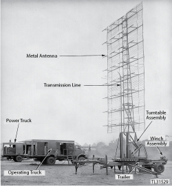
Figure 3 SCR-270 mobile radar. Source: Wikipedia.
The SCR-270 was designed to be “mobile” but required four vehicles: a K-30 operations van for the radio equipment and oscilloscope, a K-31 gasoline-fueled, power-generating truck with the transmitter power supply, a K-22B flatbed trailer and a K-32 prime mover to pull the antenna mount (see Figure 3).4 A nine man field crew operated the system: a shift chief, two oscilloscope operators, two plotters, two technicians and two electricians.
The Westinghouse Electronics Division built the modulator, power supply, transmitter and other items and RCA supplied the receiver.5 A production contract was awarded to Westinghouse to produce the full SCR-270 and 271 systems.
SCR-270 Antenna
The folding antenna mount, which was derived from a well drilling derrick, was mounted on the trailer so it could be moved. When deployed from its transportation position, it was 55 ft tall, mounted on an 8 ft wide base containing motors for rotating the antenna.4 The base plate could be rotated remotely from the operating truck to steer the antenna. Numbers 3 in high were painted on plates attached to the 8 ft diameter rotating tower base, enabling the azimuth orientation to be read through a window from the operating truck, using binoculars at times—or just estimating if something obscured the numbers.7
The antenna consisted of a series of 36 half-wave dipoles backed with reflectors, in three bays, each with 12 dipoles arranged in a three-high, four-wide stack.4 In use, the antenna was controlled by commands from the operations van, the angle being read from numbers painted on the antenna mount. The tuning on the early models was by shorting bars on parallel lines and line stretching “trombone” sections. RF to the antenna tower was carried from the operations van on a 3 in spaced copper tube parallel line to the base of the tower in a resonant line condition, terminating in a single-turn loop at the base, coupled to another single-turn loop feeding up the tower.5
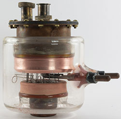
Figure 4 Westinghouse WL-530 water-cooled triode, which was also designated by the Signal Corps number VT-122. Source: lampes-et-tubes.info.
In 1940, there was not a lot of confidence that the 106 MHz antenna could be designed and built correctly, since it had not been done. Westinghouse had a field station at Sandy Hook, New Jersey, with a distant view over the waters of New York Harbor to three large gas storage tanks in Brooklyn. To tune the antenna, the tower was aimed at the center tank. One person watched the scope in the operating truck, and one climbed the antenna tower with a 4 ft length of 1 × 2 inch wood. The person on the tower banged on the trombone sections and shorting bars to adjust them, as the scope operator 150 ft away yelled whether or not the target signal was improving. When the return from the center tank was strong and the return from the side tank small, the antenna was considered tuned. The antenna was then rotated to face the Glen L. Martin plant in Baltimore, where aircraft were almost always in the air. This also checked the performance and was a chance for final tuning. After following this process with about 25 antennas, enough data was accumulated to allow pre-positioning most adjustments. Ultimately, production used a screen reflector with pre-cut elements.7
SCR-270 Transmitter and Receiver
The heart of the radar was in the operating truck. Key to the system was the primary water-cooled 8 kW continuous or 100 kW pulsed transmitting vacuum tube (see Figure 4). The transmitter used two water-cooled triodes with the grids held off at about −4500 V and pulsed up to 0 V to oscillate.7 The 15 kV plate voltage required a dual-wound ceramic coil to isolate the plates from the grounded water supply, which used distilled water to minimize leakage current and ethyl alcohol as antifreeze in the winter.
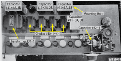
Figure 5 BC-404-C superheterodyne receiver used in the SCR-270. Source: TM-1-1510 service manual.
The first version of the prototype SCR-270 used a transmitter borrowed from the SCR-268, which delayed the SCR-268’s development. The early SCR-270 and SCR-271 consisted of the BC-405 transmitter, built around the WL-530/VT-122 tube; its modulator, called the BC-402 Keyer; and the RU-3 water cooler.8
Westinghouse delivered a pair of transmitters in January 1939, and they were incorporated into the first SCR-270 in time to be used in the Army’s maneuvers that summer. These were the first tubes with enough power to enable long range detection, which the SCR-268 did not have. The development tubes were designated 3007 and WX3007, and the final version was assigned the Westinghouse catalog number WL-530 (the WL numbers were assigned in random order). Later, the Signal Corps vacuum tube number VT-122 was assigned to the WL-530.7
The receiver was a superheterodyne design, using a special tube (A-5588-A) and RCA experimental electron multiplier in the front-end (see Figure 5). RCA built the BC-403(*) 5 in oscilloscopes and the BC-404(*) receivers. The first of the BC-404s used the RCA VT-123 “Orbital Beam tube” that evolved into the 1630/VT-128.8

Figure 6 RA-60-A rectifier used in the SCR-270 power unit. Source: TM-1-1510 service manual.
Each operating truck had a spare receiver and spare scope; however, everything was so conservatively designed that service was almost unheard of, except for the occasional modulator tube replacement.7
Power Unit
The power unit truck housed a 76 horsepower gas engine driving a 31 kW three-phase, 60-cycle generator. The RA-33 15 kV, high voltage power supply, common to both the prototype SCR-268 and 270/1, was built by L.H. Terpening and later replaced by the Westinghouse RA-39 in the SCR-270-B and the similar RA-60 in later 270/1 models.8
The power supply—about 4 ft high, 5 ft wide and 6 ft deep—supplied 15 kV at 0.5 A from a full wave rectifier, a choke and a 0.5 mF capacitor (see Figure 6).7 The power supply bottom, at the plate connection, was a cast finned structure that seated into a 3 in diameter ring mounted directly on top of the high voltage insulators on the transformer, to ensure no plate leads, caps, insulation and support problems.7
SUMMARY
Radar and microwave technology have made revolutionary advances since the 1930s. Consider the Sea-Based X-Band Radar (SBX-1), developed to provide early warning of ballistic missiles. Part of the Missile Defense Agency’s missile defense system, SBX-1 is a floating, self-propelled, AESA that uses 45,000 solid-state T/R modules (see Figure 7). Deployed in the Pacific Ocean, the SBX-1 is, ironically, serviced at Pearl Harbor. Compare this to the four vehicle, mobile SCR-270, operating at 106 MHz.
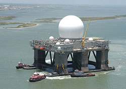
Figure 7 SBX-1 sea-based X-Band phased-array radar. Source: U.S. Navy Military Sealift Command.
Privates Lockard and Elliot stood guard over the SCR-270 radar for most of their 12 hour overnight shift, but they were able to operate the radar from 4:00 to 7:00 a.m., thought to be the most likely time the Japanese would attack. Just by chance, they kept the radar running two minutes longer and detected the Japanese planes that attacked Pearl Harbor on that infamous morning, December 7, 1941. The Opana Radar Site is now a National Historic Landmark and was designated an IEEE Historical Milestone in February 2000.9 A plaque noting the IEEE designation was installed in a small park on the grounds of the Turtle Bay Hilton at Kuilima Point. Probably unnoticed by most tourists staying at the resort, the plaque commemorates the first operational use of radar by the United States.
References
- Carole Bos, “Radar Station at Opana Point,” AwesomeStories.com, May 1, 2001, www.awesomestories.com/asset/view/RADAR-STATION-at-OPANA-POINT-Pearl-Harbor
- Andrew McKinley, “The Opana Radar Station,” Pearl Harbor Visitors Bureau, June 2, 2016, www.visitpearlharbor.org/the-opana-radar-station
- Merrill Skolnik, “History of Radar,” Encyclopedia Britannica, www.britannica.com/technology/radar/History-of-radar
- Historical Account of Radar Testing and Development from 1933 to 1942 at Fort Hancock, Sandy Hook, N.J., www.nps.gov/gate/learn/historyculture/upload/S.H.%20Radar%20report%20final.pdf
- SCR-270, Wikipedia, en.wikipedia.org/wiki/SCR-270
- Long-Range Aircraft Warning Sets, pg. 35, www.ibiblio.org/hyperwar/USN/ref/Radar/Radar-3.html
- Frederick G. Suffield, “Milestones: Opana Radar Site, 1941,” February 2000, www.ethw.org/Milestones:Opana_Radar_Site,_1941
- Don Helgeson, SCR-270, www.radomes.org/museum/equip/SCR-270.html
- Harry A Butowsky, “Opana Radar Site,” March 10, 1993, National Register of Historic Places-Nomination and Inventory, National Park Service, Retrieved May 25, 2012, npgallery.nps.gov/pdfhost/docs/NHLS/Text/91001379.pdf