
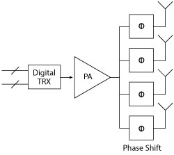
Figure 1 Classic topology for beam steering.
Smart antenna technology is a strong candidate for fifth generation (5G) wireless communications standards, but validation of system performance may prove to be an impossible task. This article will use a multi-disciplinary approach to look at the challenges of implementing a smart antenna system, in order to form an assessment of the key technical risks for developers.
Smart antennas are essentially arrays of transceivers that form radio signals into narrow beams. The trade-off is to use complex signal processing and extended physical size to improve focus. The main benefit of a smart antenna is that the focused beam can be used to reduce interference and amplify the wanted signal. In dense urban deployments, there is likely to be no direct line-of-sight path for radio communications. Multipath reflections cause complex, rapidly changing scattering patterns that a smart antenna can resolve constructively to form a spot of good coverage around a user.
When used on a High Altitude Platform (HAP), such as a satellite or aircraft, the radio signal follows a clear line-of-sight and so the objective is to form smart antenna beams that are highly directional in order to improve the link margin and reduce interference from the many other users that occupy the same extended cell.
Both small cell and HAP deployments rely on the fundamental physics of an antenna array and beam forming to improve system performance. So far, so good, but there are some challenges. To make it easier to follow the analysis, this article groups these items into the broad categories of radio, antenna and physical layers, finishing with a look at system issues. However, as you will see, smart antenna systems defy the conventional approach of breaking down an engineering design into single-disciplinary layers of functionality.
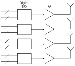
Figure 2 Modern topology for beam forming.
BASICS OF THE APPROACH
Future generations of cellular networks will make greater use of beamforming in their RF front-ends, regardless of the frequencies at which they operate. LTE Release 9 includes a provision for MIMO beam forming and future releases allow for increasingly advanced techniques to improve link budgets, especially at cell edges. Normally, LTE systems are uplink limited due to interference and propagation losses. One of the major advantages in using beam forming is that it increases rejection of noise and interference coming from other directions and maximizes gain in the direction of the user equipment (UE). UE uplink margin is limited by RF power available at the transmitter; however, the receiver compensates with downlink antenna gain. The result is greater coverage that is less constrained by interference and uplink range. Network operators are also able to run their base stations with higher downlink EIRP, providing greater SNR at the UE receiver and enabling the link to operate at a higher data rate. The benefit of reducing gain imbalances is an increase in overall cell capacity.
Beam forming at the antenna for cellular frequencies below 6 GHz can be achieved with antenna arrays. For signals with a bandwidth that is a small fraction of the operating frequency, beam squint is normally obtained by feeding each element of the array with a phased shifted analog copy of the original signal, as shown in Figure 1.
If new generations of networks are designed for operation in the 28 GHz region, as seems likely, propagation losses and building attenuation will be greater than that experienced at lower frequencies by current cellular networks. Maximizing antenna gain through the use of beam forming techniques will be important; it is quite likely that massive beam forming will be a key factor in the deployment of this technology.
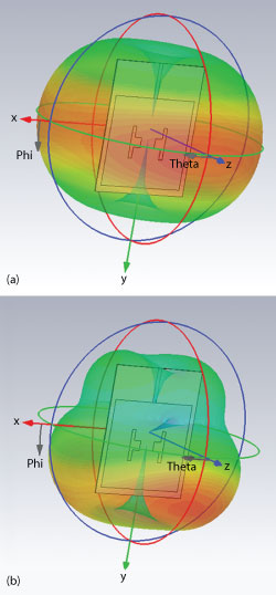
Figure 3 Propagation patterns of a single element, multi-band patch antenna at 900 MHz (a) and 2.4 GHz (b).
RADIO
Phase Shifting Architecture
Constant phase shifts across wide bandwidths can be difficult to achieve using analog techniques. Fortunately, integrated RF transceiver chips are now available with standard digital interfaces (digital TRX), which make it easier to create phase-shifted copies in the digital domain and have architectures that present multiple signals at the antenna that are independently generated by multiple DACs and up-converters in parallel paths (see Figure 2). True broadband phase shifting can be achieved in the digital signal processor (DSP), and because phase shift is performed in the digital domain, the antenna beam can be rapidly switched from one beam position to another.
Each individual PA can have lower RF output power, as the required field strength in the desired direction is achieved over the air by combining the emitted fields of the different antennas. Lower power PAs can more easily support multiband operation and can be considerably cheaper as lower cost process technologies are used. Reducing PA output power also reduces the associated costs for items such as power supplies and heat sinks.
The phased array architecture, however, requires that parallel paths be well matched as, for example, the gain and phase responses of the power amplifiers change over temperature and particularly with antenna matching. To address these issues, new systems will require sophisticated means of calibration and continuous adaptation, which should be readily achievable in the digital domain.
Multi-Band RF
Multi-band base station solutions are of interest in practical systems that must cover a range of installation requirements. While a reduced individual PA output power requirement helps enable a broadband front end, the distributed approach still needs to meet regulatory requirements to avoid interference with other users of the radio spectrum. Transmitter spectral mask and out-of-band noise and harmonic specifications are always challenging to meet and are very often achieved only on powerful base stations through the use of large and expensive bandpass filters.
ANTENNA
Antenna Element Design
The first challenge is to maintain antenna pattern stability across a wide range of operating frequencies. This is illustrated with simulations showing the propagation patterns for a single element antenna covering multiple bands (see Figure 3). In a phased array, this could be the building block of a multi-band beam forming solution. What often happens in multi-octave antennas is that, although matching can be achieved at the desired frequencies, the antenna propagation pattern varies with frequency, making it difficult to calibrate the phase response.
In Figure 3, the propagation pattern of a multi-band patch antenna shifts as the operating frequency changes. Figure 3a shows a 900 MHz pattern, with 2 dBi peak gain along the z-axis (shown horizontally). Figure 3b shows a pattern at 2.4 GHz, with 3.5 dBi peak gain angled down significantly from the z-axis. In a typical system design, this makes the selection of the antenna tilt angle more challenging.
Antenna Spacing
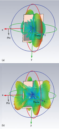
Figure 4 Propagation patterns at 900 MHz (a) and 2.4 GHz (b) with 16 cm element spacing.
Because operating bands are often spaced more than one octave apart, it is difficult is to determine the optimum separation between elements. The ideal element spacing is λ/2; however, this is not possible to achieve at all frequencies in a wideband system unless multiple redundant elements are used. Consequently, element spacing is always a compromise. The element pattern and the spacing selected for the array influences its behavior over frequency, compromising gain and side lobes. This is illustrated in Figure 4.
Figure 4a shows a neatly defined 900 MHz directional antenna radiation pattern. The eight antenna elements are spaced 16 cm apart, which is λ/2 at that frequency. Figure 4b shows what happens when the frequency is increased to 2.4 GHz with the element spacing unchanged. While both antennas achieve 12 dBi gain, the radiation pattern at 2.4 GHz becomes much less directional and is correspondingly less useful as part of a smart antenna system.
In a second pair of simulations (see Figure 5) the spacing of the eight antenna elements is decreased to 6.25 cm, which is λ/2 at 2.4 GHz. As expected, the 2.4 GHz pattern in Figure 5b shows good directional behavior with 13 dBi output, whereas the result in Figure 5a shows only 8 dBi at 900 MHz, along with degraded directional performance.
So what is the answer? Higher frequencies permit antenna arrays with more elements within the same area although the total number of transceivers that feed each of the elements grows correspondingly. A disruptive solution is in emerging technologies like metamaterials, which are demonstrating their effectiveness in producing very compact steerable antennas with high gain.
Measurements and Calibration
With a beam forming approach, the precise location of each antenna must be known, and antenna-radio chains must be synchronized, with any path length differences calibrated and adjusted. For a spot forming design, knowledge of the position of the antennas is not so important but tight synchronization is required; and, calibration of the differences between transmit and receive chains is absolutely fundamental. Spot forming systems also require accurate measurements of the dynamically changing radio environment.
PHYSICAL LAYER
Computational Complexity
The obvious challenge associated with physical layer of a smart antenna system is the increase in computational complexity. When compared to a single omni-directional antenna, the next generation, line-of-sight smart antenna is estimated to be on the order of 100x more complex. In a non-line-of-sight, multi-path scenario, there is even a greater increase in complexity required to form a “spot” of coverage – approximately 100,000x. These numbers may seem problematic, but in the long term Moore’s law to is expected to make them increasingly achievable.
Power Consumption
The difficulty in optimizing smart antenna systems is that no single part of the system works in isolation. In a conventional system with a small number of antennas, power consumption is dominated by power amplifier transmit power requirements. When scaled up to hundreds or even thousands of antenna elements, the total RF output power is the same, and the total PA power doesn’t change significantly. The power consumed by the remaining analog and digital circuitry, however, increases linearly with the number of elements, which could be 100x to 1000x.
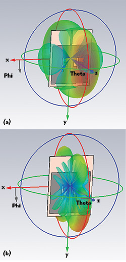
Figure 5 Propagation patterns at 900 MHz (a) and 2.4 GHz (b) with 6 cm element spacing.
This is particularly challenging for HAPs, as a key design parameter is to optimize for a limited power budget. It is also a challenge for small urban cells and 5G, since mobile operators are looking to decrease operational expenditure (OPEX). The optimization of power consumption becomes a multi dimensional problem with PA power, antenna count, DSP calculation complexity and media access control (MAC) scheduling all affecting performance.
Coordination is Not Just Within the Physical Layer
Obviously, signals from each antenna element must be combined with those from all of the other elements to produce the desired beam shape, which requires data to be copied accurately within the physical layer. However, there is a challenge to coordinate this operation across a number of separate logic devices, causing the implementation to break out of a neatly layered approach. For example, when physical layer operation is extended across many devices to provide coordinated multipoint behavior, there is an associated cost for the additional data transfer and accurate synchronization between devices.
A further complication occurs in the scheduling of packets for transmission. Because the shape of the cell has been deliberately skewed, there is a timing-varying problem with cells potentially causing brief but intense periods of interference for neighboring cells. The best way to mitigate this problem effectively is for schedulers within peer MAC layers to communicate and coordinate their actions. We should expect packet routing to become more predictive and for applications to become more aware of the smart behavior. The overall effect is that management of the radio resources is rapidly becoming a task that is distributed throughout the layers of the architecture. This presents two problems: first, the architecture breaks the simple layered approach to module design and becomes multi-disciplinary; and second, there is communications overhead to maintain coordinated operation between separate peer entities.
SYSTEM
A challenge that may not be solvable in a practical product is system validation.
System validation is needed early in the design cycle to prove that proposed system gains live up to the promises of the theoretical analysis. No one can afford to deploy a smart antenna system and hope to resolve complex, interdependant issues in the field.
Validation is especially tough for the most difficult use cases, which show up only when large numbers of users are accessing the network. The problem is how to scale up existing test strategies to reproduce networks with multiple base stations and thousands of transceivers, all cooperating closely in real time. The test network must operate in real time, in an automated and repeatable way that allows different system configurations and optimizations to be accurately measured and benchmarked across a range of conditions.
Conclusion
Smart antennas are an exciting new technology, but system design challenges must be overcome. To avoid unacceptable increases in overall solution size and current consumption, a real world solution needs to balance antenna performance enhancements against the complexity of the radio and physical layer.
It is unlikely that a 100× to 1000× increase in either size or power consumption will be acceptable; therefore, workable solutions are likely to leverage Moore’s Law by maximizing the level of digital integration and miniaturizing analog elements by incorporating them in a module that integrates all duplicated components when an antenna element is added. At 5 GHz and above, it becomes practical to implement a reasonably efficient antenna radiating element on a chip scale module. An attractive system solution, at these frequencies, might be a single ASIC incorporating all physical layer functions up to the RF digital interface and an array of front-end modules each incorporating a radio, a power amplifier and an antenna radiating element. The challenge then becomes: how do you validate the real world performance of such a system?