
In “An Introduction to Passive I/Q, Single Sideband and Image Reject Mixers,” published in the December 2015 issue of Microwave Journal, we highlighted the difficulty in maintaining high performance over a broad bandwidth in these special mixers. High performance requires precise amplitude and phase balance over the bandwidth of operation. Any imperfection in the phase balance of the LO or the amplitude or phase balance of the I/Q channels will lead to imperfect sideband cancellation in a single sideband (SSB) or image reject (IR) mixer or imperfect rejection of the unwanted channel in an I/Q mixer. Maintaining this balance is the subject of ongoing research and development. In this article, we review the state-of-the-art in quadrature phase shift generation. We will also discuss techniques to compensate for inevitable imperfections in quadrature signal generation and combination.
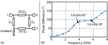
Figure 1 Branchline coupler schematic (a) and phase response (b).
The following approaches to creating a quadrature phase shift are discussed, listed from worst to best and judged by the following characteristics:
- Achievable balance over the bandwidth
- Size and achievability in planar or integrated forms
- Suitability for data (i.e., on the RF/IF port in addition to the LO port)
- Insertion loss, isolation and power handling
- Difficulty and cost to implement.
Power Split with Delay Line
Easy to implement but extremely narrowband, this is the trivial case where you simply pass the signal through a power divider and then time delay one side. For any application with a fixed frequency LO, this is a straightforward way to obtain a very accurate 90 degree phase differential, especially if you can tune the delay. It works only at a single frequency, so it is unsuitable for data, yet great for a single frequency LO.
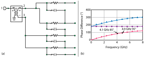
Figure 2 Polyphase filter quadrature splitter schematic (a) and single stage phase response (b).
Branchline Coupler
Slightly broader band and easy to implement in a planar microstrip circuit, the basic branchline coupler consists of four quarter-wave microstrip sections arranged in a square ring, with different impedances on adjacent sides (see Figure 1). This can theoretically provide perfect quadrature phase, but only over a small bandwidth. The single stage coupler has a 33 percent bandwidth with a 5 degree phase difference (see Figure 1b). This performance is adequate for many communications applications as it can pass narrowband data with high power.
Schiffman Phase Shifter
The Schiffman phase shifter is an unconventional but powerful technique for some applications. It applies a broadband 90 degree phase shift (not a time shift) to one signal, while another signal is passed through a matched time delay. It can provide multi-octave bandwidths with some difficulty and has a high power handling capability. It works for LO signals and IF/RF data as well. It is somewhat esoteric and can be challenging to design.
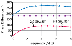
Figure 3 Two stage polyphase splitter phase response.
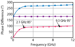
Figure 4 Three stage polyphase splitter phase response.
Polyphase Filter Quadrature Splitter
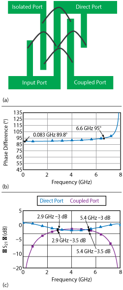
Figure 5 Lange coupler layout (a) phase response (b) and insertion loss (c).
This quadrature phase splitter makes the list for one significant reason: it is probably the most ubiquitous quadrature splitter on the planet. CMOS chip makers frequently tie polyphase splitters with Gilbert cell mixers to create billions of inexpensive I/Q modulators for cellular and Wi-Fi applications (see Figure 2). They are perfect for CMOS implementation because they use lumped elements, have differential inputs and occupy a small area; however, the high loss and frequency limitations of CMOS circuits make them unsuitable for microwave applications.
The polyphase filter is fairly complicated (see Figure 2a), yet because of its popularity, there is a tremendous amount of information available about both analog and digital forms. One major drawback is loss. In addition to the 6 dB splitting loss (for a four-way split), a single stage polyphase filter has about 4 dB of additional loss while creating only a narrowband quadrature signal (see Figure 2b). Bandwidth can be improved by adding a second stage (see Figure 3) and a third stage (see Figure 4) to create a very broadband phase shift; however, the cost is that each stage adds another 3 to 4 dB of insertion loss. The broadband three stage phase shifter has over 10 dB of insertion loss in addition to the 6 dB splitting loss.
Lange Coupler
Due to the Lange coupler’s quasi-planar nature, it is the most common device used with balanced MMICs such as amplifiers and I/Q mixers. The fundamental problem with planar couplers is that edge-coupled microstrip lines are very weakly coupled unless the gap between them is very small. This is limited by the fabrication tolerances of the process, so 3 dB couplers are difficult to realize. Lange couplers solve this problem by using wire bonds or air bridges to connect different fingers of an interdigitated coupling structure (see Figure 5).
The four finger Lange coupler shown in Figure 5a has very good phase and amplitude balance and low insertion loss and covers slightly more than an octave bandwidth. Amplitude balance can be improved by adding more fingers, but this comes at the expense of phase balance. Overall, the Lange coupler is an excellent choice, especially for a quasi two-dimensional structure. It can be used for a broadband LO signal or RF/IF data, can be cheaply printed onto a MMIC or other planar circuit and is relatively easy to design. The only major drawbacks are lower power handling, due to its wire bonds or air bridges, and slightly less bandwidth than the previous two options.
Digital Frequency Divider
For a perfect quadrature ultra-broadband phase shift, it is difficult to beat a digital frequency divider. The digital circuit is very simple: it just takes a double rate clock and switches one output on the rising edge and one on the falling edge, resulting in two outputs in quadrature with each other. It is implemented with two D flip-flops, with the inverted signal connected to the input of one (also called a T flip-flop) as shown in Figure 6. Since it is fabricated in fast, differential SiGe, it can provide all four phases of the output signal from DC to as high as 30 GHz. In addition to needing a double rate clock, there are a few other drawbacks. Since the circuit is limiting, it is not suitable for analog inputs, so it cannot be used as the IF hybrid in an IR/SSB mixer. If there is any amplitude noise, duty cycle distortion or amplitude distortion on the input, it will show up as phase noise or distortion on the output.
In general, this is not a very good device as a quadrature splitter, but it is perfect for creating a quadrature LO drive for an I/Q mixer. This is what is frequently used in low frequency silicon RFICs for LO clock generation, which means it is also ubiquitous.
3 dB Quadrature Hybrid Coupler
The 3 dB quadrature hybrid coupler is the “gold standard” for quadrature signal generation. It can operate across a broad bandwidth (e.g., 2 to 26 GHz), has excellent balance in both amplitude and phase and can be used as the RF or IF hybrid of an image reject or single sideband mixer for better than 20 dB of rejection. Ideally, it is built in a tri-plate stripline construction, which has the physical advantage of matching the dielectric constant around the circuit while handling 20 W or more of CW power. Figure 7 shows the basic coupler layout, along with the phase deviation and loss performance that can be achieved.
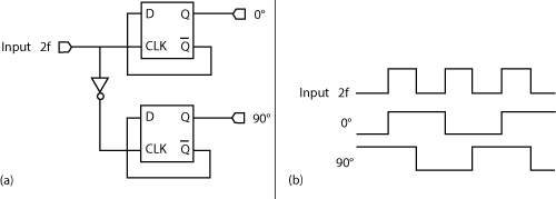
Figure 6 Digital frequency divider schematic (a) and phase response (b).
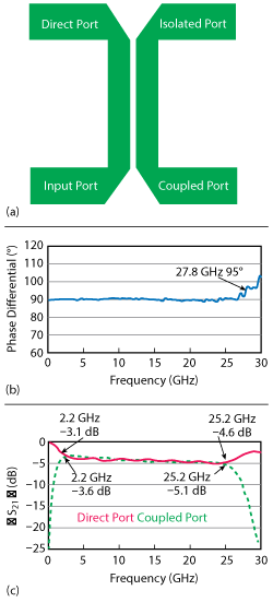
Figure 7 3 dB quadrature hybrid coupler layout (a) phase response (b) and insertion loss (c).
All stripline directional couplers can provide a 90 degree phase shift, but it is difficult to achieve strong enough coupling to create the 3 dB split necessary for amplitude balance. Integration requires broadside coupling for a high coupling coefficient in a system with good dielectric properties. The combination of stringent materials requirements and high design difficulty have limited their realization in a multi-octave planar form to just the Microlithic1 series of mixers.
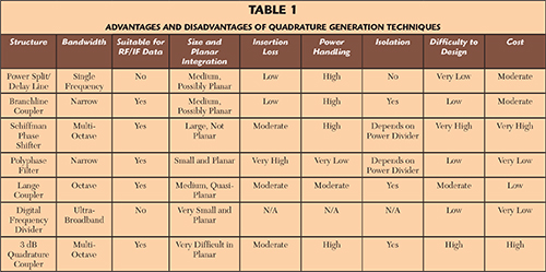
Table 1 summarizes the advantages and disadvantages of the quadrature generation techniques discussed.
Compensating for I/Q-SSB-IR Imbalance
Unfortunately, even the best quadrature phase shift achievable will always have some imperfections due to fabrication tolerances, design limitations, material variability over temperature and aging over time. Fortunately, any imbalance in the LO phase of an I/Q-SSB-IR mixer can be compensated on the IF side, and vice versa. What follows is a description of several techniques, beyond component design and selection, that are commonly employed to overcome these limitations.
DC Offsets
The application of a DC voltage to the IF port of a double balanced mixer changes the bias conditions of the diode rings inside. Specifically, two of the diodes turn on at a higher voltage, and two of them turn off at a higher voltage. Figure 8 shows an oscilloscope screenshot of the output of a microwave double balanced mixer with no DC bias and with +0.5 V applied. The DC voltage degrades conversion loss without changing the phase, allowing easy variation of amplitude balance on one side of an IQ mixer.2
Unfortunately there is a trade-off. The application of a DC voltage also degrades LO-to-RF isolation; as sideband suppression is improved, LO suppression is reduced. Since the LO is always closer than the unwanted sideband, this generally doesn’t make sense for a single sideband mixer. With the mixer shown in Figure 9, sideband suppression is increased from about 19 to 23 dB by adding an offset voltage, then again to approximately 50 dB by combining phase manipulation with the DC offset. The penalty is increasing LO feedthrough from -30 to -3 dBm, overpowering even the desired sideband. This technique can be used without penalty for image reject mixers, however, since the LO is out of the band of the IF output. If phase balance is much better than amplitude balance, to begin with, then this technique can yield improvement. In most situations, the benefits will be quite limited, however.
LO Phase Manipulation
The error terms for sideband elimination are all dependent on φand ε, meaning that the LO phase can be manipulated to completely eliminate the erroneous sideband. This can be done without the penalty to LO feedthrough that comes with DC biasing, since the phase of the incoming LO does not affect LO to RF isolation. The problem, however, is that this cannot always be done in a convenient manner. If the I/Q mixer is built as a bolt-together solution, then the phase can be manipulated by varying line lengths or using a phase trimmer. If the I/Q mixer is integrated, however, it is more difficult. For a mixer in a planar integrated form,3 LO phase can be trimmed by applying ceramic, absorber or other microwave tuning elements while observing the sideband suppression.
ADC/DAC Phase and Amplitude Correction Registers
This is the predominant approach for analog I/Q compensation (see Figure 10). Amplitude and offset correction registers are generally built into DACs that are designed for communications, arbitrary waveform generation and software defined radios. This makes them readily accessible for IF amplitude and phase manipulation. The phase can also be manipulated in digital implementations. Since the amplitude and phase terms are sufficient to completely eliminate the sideband error terms, the only limit to the achievable sideband suppression is the quantization noise of the DAC and the time, temperature and frequency variations between the calibration point and the transmitted signal.
Some ADCs are also designed to receive I/Q data and perform another down-conversion, particularly those intended for software defined radios. The phase control in these ADCs may be performed on the internal oscillator. For more information, one can consult the (usually very detailed) datasheet of a dual channel high speed ADC.
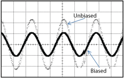
Figure 8 Double balanced mixer output when biased and unbiased.
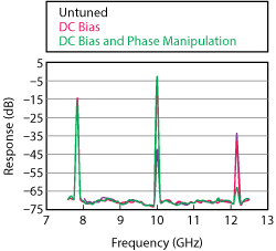
Figure 9 Trade-off between sideband and LO suppression.
Digital Compensation
This is the ultimate in I/Q compensation techniques. As we have seen with fiber optic links, wireless links and other modern data standards, it is easier and less expensive to use millions of transistors to digitally compensate for a bad signal than to create the analog channel necessary for a good signal. Any deterministic impairment can be pre- or post-compensated, and sideband suppression is definitely deterministic. The basic approach for sideband suppression is to simply receive both I and Q channels, estimate the distortion coming from the Q channel to the I channel and then subtract this estimate from the I channel.

Figure 10 ADC/DAC phase and amplitude correction.
There are numerous methods to perform this digital compensation with different cost tradeoffs. For example, some techniques are “blind,” meaning they do not require a separate receiver to estimate the error vector magnitude; some require training sequences, while others do not; and some are capable of compensating for errors in addition to I/Q imbalance, such as fading and DC offset. There are many references on this topic, including several books. Most contain dense math and advanced digital signal processing algorithms. One excellent resource is Marcus Windisch’s thesis,4 in particular Chapter 4.
CONCLUSION
This article covered two topics central to the design and performance of passive I/Q, single sideband and image reject mixers: quadrature signal generation and compensation of amplitude and phase imbalance. Several ways to generate quadrature signals were described, with the 3 dB hybrid coupler demonstrating the greatest capability. It is broadband, has excellent amplitude and phase balance and can be used as the IF hybrid of an image reject or single sideband mixer to obtain high rejection. What the future holds for high performance I/Q-SSB-IR mixers is uncertain; it is likely to lean heavily on digital LO generation and digital compensation techniques.