
With an ever-increasing performance-to-price ratio, coupled with unprecedented, precise radio frequency (RF) signal control, practical use cases for solid-state RF technology are expanding to include heating and power delivery. As a result, the technology is penetrating fields that were previously considered impossible, such as tube-based systems (for example, automotive ignition, medical imaging and cancer treatment) or high barrier markets (for example, industrial and consumer microwave furnaces/ovens) that are dominated by cost-effective magnetron sources.
|
Related White Paper:
The VSX3622, a 1.5 kW X-Band GaN Power Amplifier |
The new markets present ultra-high volume opportunities for businesses operating directly and peripherally in the RF technology industry. They also present alternative revenue potential to currently maturing markets such as cellular infrastructure.
Figure 1 Typical data transmission block diagram.
The design of solid-state RF energy systems requires engineering knowledge that is not generally available, due to RF engineers occupied with “linearized amplifier” systems for data transmission or concerned with magnetron sources for heating applications. There is a general lack of design knowledge with respect to applying solid-state generated RF to additional, less-focused-upon RF energy systems.
This article will cover a number of economic and technical challenges associated with the system design of a solid-state RF energy system. It will also present the RF Energy Alliance’s vision on how the solid-state PA module will develop into a commodity in the next three to five years. Throughout the discussion, RF and microwave are used synonymously.
Figure 2 Magnetron tube powering RF energy application.
Technology Background
All modern communications — cellular telecommunications, radio and video broadcasting, Wi-Fi and Bluetooth at a lower power level — make use of complex, highly modulated RF signals that are generated and amplified by solid-state, semiconductor devices. Solid-state technology replaced the legacy, tube-based technologies some time ago for reasons of reliability and ease of use.1
Solid-state RF generation and amplification technology can also be used to “power” a localized chemical or physical process, rather than to transmit data. This gives rise to the notion of “RF energy” applications in contrast to the data transmitting uses. Examples of RF energy applications are industrial heating,15,16 microwave furnaces,11,15,16 RF plasma lighting,4,5 automotive plasma ignition,6 microwave assisted chemistry,17 medical cancer treatment,7 and many others.
Figure 1 shows the different building blocks for high power RF generation and radiation for either data transmission or RF energy use. An important distinction between the data transmission systems and the RF energy systems, shown in Figures 2 and 3, is the need for highly modulated signals in the data transmission case. Power amplifiers must run “backed-off,” which means that they are less efficient than amplifiers that run saturated, which is easily achieved for RF energy applications. RF energy applications typically make use of an RF-tight cavity that contains the load to be processed and into which the RF is irradiated with an antenna. In contrast, the RF used for data transmission is irradiated into free space (see Figure 1).
Figure 3 Solid-state powered RF energy application.
Another important difference between tube-driven and solid-state-driven RF energy applications (see Figures 2 and 3) is the presence of feedback for the solid-state driven applications. Forward and reflected power levels can easily be assessed; energy levels put into the load can be readily measured and tracked during the process.
The next difference is the capability of solid-state systems to change the frequency — typically within an industrial, scientific and medical (ISM), unlicensed frequency band. The application controller is able to determine the exact cavity/load conditions during the process (VSWR), and can react accordingly.
Solid-state systems are relatively flexible with respect to the number of channels and/or solid-state power amplifiers “around” a processing cavity. This allows power scaling with the number of channels, and the independent (different frequencies per channel) or coherent (same frequency with particular phase offset) RF drive of the process. With the multimode cavity (a high Q structure), this offers system designers a choice to actively control the electromagnetic field distribution inside, which is one of the formidable technological challenges to these systems.
Figure 4 Block diagram of a solid-state RF generator system.
A complete solid-state RF generator subsystem typically consists of:
- Small-signal generation part optionally co-located with a microcontroller
- High power amplifier (basically a gain block) connected to a heat sink
- Power supply to deliver the various voltages and currents to drive the respective electronics.
Figure 4 depicts a block diagram for such a system. The “RFout” connection leads into an RF applicator that is a cavity or otherwise confined environment holding the medium to absorb the RF radiation and provide the necessary EMC shielding.
The solid-state RF power generator allows complete freedom and control over the frequency, output power level, phase and “modulation” of the RF signal. “Modulation” here means switching the RF signal (on/off) over time and/or changing the output power level — both can happen very quickly within microseconds. Furthermore, feedback on forward and reflected RF power is usually built into the amplifier; in more involved cases, even phase measurements can be carried out for complex S-parameter measurements.

Value Proposition
The previously mentioned measurements, extreme degree of control of RF signal parameters and solid-state semiconductor nature of the system lead to the following possibilities and advantages over magnetron-powered systems:
- Great reproducibility and repeatability
- Precise control over power levels and energy doses
- Enhanced process control — higher yields
- Very high reliability of the generator — no unpredicted down time or production loss
- No single point of failure in industrial or scientific systems
- Utilization of full ISM band bandwidth
- Dynamic frequency “hopping” and/or phase shifting
- Homogeneous energy distribution inside cavity
- Efficient use of the generated RF energy
- Very agile control of the RF signal (frequency, phase, on/off, gain, etc.)
- Fast load condition feedback to tune RF signal and process; for example, prevent damage upon arcing
- Spectrally clean frequency source; predictive use of frequency hops; benefit to co-existent wireless communications technologies
- Low voltage electronics – easier maintenance, easier integration, smaller size
- Compatible with electronics cost base.
Economical Aspects
Although the process advantages of the technology are compelling, widespread use has yet to catch on. So far, the technology can be found within medical and professional applications. Industrial use (replacing large magnetron tubes) is slowly taking hold, and applications for the consumer space are currently in development.8 The foremost reason for the slow adaption is cost — next to the knowledge gap.
Figure 5 Size/volume development of PA modules over time.
The RF Energy Alliance8 has set out to tackle this chicken-or-egg problem by bringing together all stakeholders in the solid-state RF supply chains and ecosystems. The organization presents a leadership role to create awareness and roadmaps to overcome these barriers to entry. The alliance works towards standardization of RF energy components, such as PA modules, their respective software and hardware interfaces, integration with power supplies, cooling systems and overall spec points. This will enable the original equipment manufacturers (OEM) to focus on the application development, knowing exactly what will be available in terms of functionality, size, efficiency and price. This strategy avoids investments in the “wrong” technologies, allows perfect timing of volume manufacturing investments and greatly simplifies the integration work for the OEM. Ideally, the resulting ease of use will give rise to swift development of current and new applications such as RF lighting, medical ablation and RF plasma ignition for automobiles.
Existing applications for the higher volume markets will benefit from standardization. Reduced prices, improved performance and standardized components will also allow a competitive landscape with small barriers to switch among hardware suppliers. The latter may cause some concern, but the opposite is true: the markets are so large that there will be enough business for a number of suppliers. The OEMs will demand a flexible supply chain with at least two suppliers so that manufacturing and/or quality problems can be alleviated, ramp-ups can be faster and the business risk reduced. Standardization will enable seamless transitions.
The Alliance is currently finalizing its “power amplifier roadmap” that will specify sizes, efficiencies, RF output power levels, RF power measurement and ruggedness, cost targets and availability, amongst various other functionalities. Figure 5 shows the development of the power amplifier module volume (length × depth × height) across the currently foreseen generations. RFEA-Gen1 corresponds to currently available, state-of-the-art PA modules. We see a stunning reduction in size that will greatly enhance the designer’s freedom to place the PAs.
Interestingly, the target cost for the PA modules follows a similar graph. The Alliance targets $12 per 300 W power amplifier module with 70 percent efficiency in the near future. As unrealistic as this number currently sounds, the Alliance remains confident and defends this claim.8
Designing an RF Energy System
When it comes to conceiving an RF energy system, a system architect must cover the “usual suspects” like power supplies, thermals, digital interfaces, microcontrollers and firmware, as well as the intricacies around RF signal generation, amplification and “injection” into the applicator. Here, we will concentrate on the RF system aspects, rather than the more common ones:
- Applicator used
- Number of RF channels
-
RF signal generation (frequency, gain, phase, resolution, etc.)
Total RF power required - PA thermals
- RF operation
- Ruggedness
- Homogeneous energy distribution
- Real-time process control.
Applicator
The “applicator” in the RF Energy system denotes the enclosure or, more generally, the environment in which the RF radiation is applied towards a particular load. The load can be most anything: to make sense, however, it should absorb all or at least part of the incident radiation.

Figure 6 Schematic of applicator with two RF feed lines, i.e., two channels.
Figure 7 TM020 cavity to process liquids.10
In general, the applicator environment is a metal casing that encloses the load to define the “active processing volume” and to prevent RF radiation leaking into the environment (see Figure 6). RF energy systems are running up to megawatts of RF power – there is no room for leakage. A more subtle requirement along these lines is imposed by the necessary coexistence with communication technology like Wi-Fi, Bluetooth and ZigBee. The applicator brings about a number of design choices, boundary conditions and issues concerning the industry.
Enclosed Volume = Cavity
In our frequency range of interest, typically enclosed volumes with metal walls are used to establish a resonating structure with quality factor Q and maintain eigenmodes, that is standing wave patterns, which in turn depend on the geometry of the cavity in connection with the wavelength of the irradiated RF.9
On the one hand, a cavity width cannot be smaller than roughly half the wavelength of the RF signal to be injected; below this cutoff, no RF energy can be injected. Above this cutoff, “single mode” cavities take shape, which can be round or rectangular waveguide structures. Depending on the chosen geometry, either transverse electric modes like TE101 or transverse magnetic modes TM010 develop that can be used for efficient energy transfer and/or sensitive measurements of dielectric properties. To give an example (see Figure 7), liquids can be heated efficiently when flown through the highest field volume inside the cavity, in this case a TM020 applicator.10
On the other side of the spectrum, there are cavities that are large in comparison to the deployed wavelengths: multi-mode cavities. As the name indicates, a number of modes can be excited within the cavities depending on the geometry, the absorption of the load and the RF frequency. Generally speaking, the larger the cavities with respect to the wavelength, the more modes can be formed. For a typical household 2.45 GHz magnetron cavity, the number of modes is on the order of 15.9
The frequencies at which resonance can occur for an empty cavity are governed by the following equation:
where f0 (Hz) is the resonant frequency of mode TEmnk or TMmnk for a rectangular cavity with dimensions a, b, and l (meters), and c0 is the speed of light. Please note that “double-zero” modes cannot exist and others may be degenerate (TM and TE modes at the same frequency).11
Figure 8 Empty cavity return loss sweep.
Ruggedness
The existence of the modes also implies RF generators can only deliver energy into the cavities at frequencies corresponding to modes — at other frequencies, the cavity is not impedance matched and the RF power is reflected. This behavior is shown in Figure 8: for an empty cavity (zero or little dissipative load inside) a return loss sweep across the frequency range of 2.4 to 2.5 GHz reveals a number of dips where the cavity is actually matched.
This emphasizes a demanding requirement for all types of RF power amplifiers feeding various RF energy applications. The amplifiers need to be extremely rugged, because more often than not, RF power may simply be reflected. However, it must be accommodated in order to avoid destruction of the power amplifier. A circulator may be used for that purpose. Ideally it should be designed out of the PA to save cost and size. However, without the circulator, the PA design needs to be rugged enough to withstand worst case VSWR ratings, a challenge for both the PA design as well as system level control. For a single channel system (just one amplifier delivering the RF power), the maximum reflected power is as large as the PA’s output power. The required ruggedness specification can easily exceed a 10:1 VSWR. This appears manageable with the latest LDMOS12,13 and GaN transistor technologies.
In case of multi-channel systems (more than one amplifier delivering power), the amount of reflected power is not limited to the output of a single PA; rather, it depends on the “matching” of a particular PA via the cavity to the peers surrounding the cavity. Proper system level control algorithms and low level (at the PA), fast protection mechanisms need to be built-in to avoid catastrophic failures.
Number of Power Amplifiers
The previous discussion assumed “one” and “more than one” power amplifiers delivering power into a cavity. However, power scaling is a viable option. Current LDMOS power transistors deliver up to 300 W of power at 2.5 GHz out of small packages (2 cm2). Using a household microwave oven as a reference, three or four RF generator chains are needed to match the power of a typical magnetron.
The total power should always be determined based on the process’ needs. The 1 kW for household microwaves, for example, is not an efficient means to cook — it is too much power for most of the cooking/reheating needs. Limited regulation capabilities of the magnetrons do not help either. The surface of food gets superheated most of the time, which leads to dry and overcooked food. 500 to 600 W completely suffices for this purpose. The exception here is for defrosting.
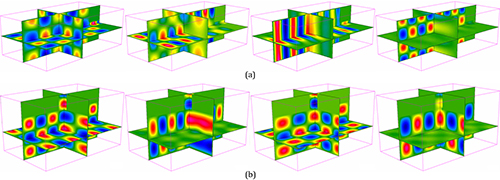
Figure 9 Patterns of instantaneous electric field in the rectangular (612 × 400 × 300 mm) cavity excited by a rectangular waveguide centrally connected with the side wall (a) and the top wall (b) at four resonant frequencies in the range of 2.35 to 2.55 GHz.14
One could argue that it might be easier to combine all the PAs’ output powers externally or even combine a number of final power transistors inside a single PA module. For the latter, the unwieldy 7/16 connector and associated cable would not be easily integrated for residential use. For industrial use, this is certainly an option, yet still demands very precise design and manufacturing of the high power transmission line structures inside the PA. The main argument to use multiple RF generators, however, is because of the modes inside the cavity and the intention to achieve a homogeneous energy distribution inside the cavity and inside the load.
Homogeneity
The previously discussed modes in multi-modal cavities, which are typically used for heating, cooking and drying processes, do not by themselves provide homogeneous heating inside the load. On the contrary, the localized energy distribution associated with a particular mode will only deliver energy to dissipative loads at those spots. Figure 9 shows the electrical field distribution inside a cavity for various possible modes for a particular cavity.14 In this case the fields were calculated using the real cavity dimensions and antenna openings, providing a more realistic result than using the empty cavity formula. A single mode will not provide homogeneity, but a number of complementary modes will. By tuning into various modes, the fields inside the cavity can be stirred to an extent that promotes homogeneous energy delivery to the food. The shape and dielectric constant of loads play an important role with respect to homogeneity as well (see Figure 10). Via frequency and phase we have a clear handle on the energy distribution inside both the cavities and load.
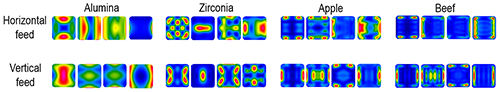
Figure 10 Patterns of dissipated power in the central horizontal plane through the rectangular (100 × 100 × 20 mm) load centered on the FR4 shelf in the cavity (see Figure 9) at four resonant frequencies in the range of 2.35 to 2.55 GHz.14
We have addressed frequency agility, but the relative phase of the RF signal between the channels in case of a coherently-driven system must be addressed. Coherency here means RF signals for different channels are derived from the same local oscillator, thus running at the exact same frequency. The inter-channel phase difference now becomes a parameter to vary. It is easy to see this phase difference is necessary in this case to optimize the energy delivery — the excitation of a mode needs to happen “in sync” out of the various antenna ports. Electromagnetic simulations (and measurements) show a variation of the phase also affects energy distribution inside the cavity and can be used to enhance homogeneity, albeit less strongly than frequency variations. In that sense, a multi-channel system starts to resemble an “antenna array” which can be electronically scanned.
Briefly returning to the incoherent control mode (different channel frequencies), one should take good care of the intermodulation products created. Out of band frequencies should be avoided unless the shielding comes to rescue. Depending on the position of the various antenna ports, not all possible modes inside a cavity will be excited. The very shape of the mode and its character at the opening of the antenna port may be at odds. In any case, a return loss sweep (see Figure 8) will bring clarity to the current cavity/load situation. Algorithms to promote homogeneity and efficient energy delivery (i.e., at low return loss values) can then be devised and used for proper process control. Given the speed of microcontroller-based systems, the scanning and algorithm development will take very little time and does not interfere with the main process.
The clear discernibility of modes or resonances is a typical feature of a more or less empty cavity (high Q). An increasing dissipative load becomes part of the electrical length of the cavity and the resonance conditions change. Existing modes are shifted to lower frequencies, broaden and eventually vanish completely (low Q),10 because the RF signal is directly absorbed and does not have a chance to develop a standing wave pattern. In the extreme case of a fully loaded cavity, we end up with no mode spectrum and the homogeneity now becomes a function of penetration depth into the load. Slow thermal conduction or convection inside the load will reduce the temperature gradients.
Conclusion
There is a great opportunity to develop a new industry revolving around RF energy applications, and an equally impressive number of potential job opportunities to deploy this technology. The technologies are available, a number of promising applications are being developed and, if things are done correctly, we will soon find this clean, efficient, highly controllable, contactless and selective energy source in our daily lives.
The implementation in a number of possible applications is currently limited by economics and our ability to realize them, rather than by the technology itself. The envisioned standardization driven by the RF Energy Alliance will help reduce barriers to entry and enable the applications of the technologies.
The challenges to build those systems are numerous, requiring significant knowledge on electromagnetics, control and applications. The overall application is an intricate interplay of RF sources with an applicator and variable load/processing conditions in the cavity. The design ingredients covered here hold for all kinds of RF energy systems. Be it an automotive plasma ignition source or an industrial heater, the RF source needs to continuously adapt to the changing cavity/load/resonance conditions to “stay tuned."
References
- F.H. Raab, P. Asbeck, S. Cripps, P.B. Kenington, Z.B. Popovic, N. Pothecary, J.F. Sevic and N.O. Sokal, “RF and Microwave Power Amplifier and Transmitter Technologies – Part 1,” High Frequency Electronics, May 2003, pp. 22236.
- M. Mehdizadeh, “Engineering and Scale-up Considerations for Microwave Induced Reactions,” Res. Chem. Intermed 1994, 20(1), pp. 79284.
- http://en.wikipedia.org/wiki/Microwave_oven.
- M. DeVincentis, G. Hollingsworth and R. Gilliard, “Long Life Solid-State RF Powered Light Sources for Projection Display and General Lighting Applications,” IEEE MTT-S International Microwave Symposium Digest, June 2008, pp. 149721500.
- K. Werner and S. Theeuwen, “RF Driven Plasma Lighting: The Next Revolution in Light Sources,” Microwave Journal, December 2010, pp. 68274.
- K. Werner, H. Heuermann and A. Sadeghfam, “The Potential of RF Energy for the Ignition of Microplasmas,” High Frequency Electronics, November 2012, pp. 38243.
- J.F. Bakker, M.M. Paulides, A.H. Westra, H. Schippers and G.C. van Rhoon, “Design and Test of 434 MHz Multi-channel Amplifier System for Targeted Hyperthermia Applicators,” Int. J. HyPerthermia, March 2010; 26(2), pp. 1582170.
- www.rfenergy.org.
- D.M. Pozar, “Microwave Engineering,” Wiley, New York, 2004.
- M. Mehdizadeh, “Microwave/RF Applicators and Probes For Material Heating, Sensing and Plasma Generation,” Norwich, N.Y., William Andrew, 2009.
- T.V. Chan and H.C. Reader, “Understanding Microwave Heating Cavities,” Artech House, Boston, Mass., 2000.
- www.rfmw.com/data/NXP_XR_white_paper_November_2013.pdf.
- www.freescale.com/training/online-academy/rugged-ldmos-transistors-for-ism-and-broadcast:WBNR_RUGGEDLDMOS.
- V.V. Yakovlev, Frequency Control Over the Heating Patterns in a Solid-State Dual-Source Microwave Oven, IEEE MTT-S International Microwave Symposium Digest, Phoenix, Ariz., May 2015, 978-1-4799-8275-2/15.
- R.J. Meredith, “Engineers’ Handbook of Industrial Microwave Heating,” IEE, 1998.
- J. Thuery, “Microwaves: Industrial, Scientific and Medical Applications,” Artech House, 1992.
- N.E. Leadbeater, “Microwave Heating as a Tool for Sustainable Chemistry,” CRC Press, 2011.