
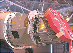
Figure 1 Raytheon AN/APG-79 AESA (courtesy of the U.S. Navy).
Many think that radar is a mature technology where nothing has changed over the past decade. But many new developments have taken place and radar is still evolving today. As the technology advances, new applications appear in both military and consumer markets. Sometimes the need pulls the technology along, and sometimes new technology makes a new application possible.
Radar has been highly influenced by microwave technology and, likewise, the development of microwave technology has been significantly affected by the needs of radar. Exciting developments have occurred over the last few years in system architecture and algorithms, waveforms, signal processing, materials, circuits, electromagnetics and device design, some of which will be addressed in the following sections.
Radar requirements and design adjust to meet the mission needs and the constraints of the operating platform. New technology that boosts performance to more effectively meet customer needs is phased in as it becomes practical, meeting an acceptable technology readiness level.
Airborne Systems
Airborne systems typically seek the best performance possible in a constrained size, weight and power (SWAP)envelope operating in a severe environment, so they tend to use the most advanced technology. A recent revision of Stimson’s “Introduction to Airborne Radar”1 provides a valuable overview.
Figure 2 Array sizes and module count for various aircraft platforms (source: Defense Science Board, September 2001).
Active electronically scanned arrays (AESA) are revolutionizing the performance of modern radar systems, enabling an unprecedented degree of operational flexibility. AESA technology is particularly advantageous in fighter radars due to the overall superiority in terms of performance, reliability and life cycle cost. With the development of device and packaging technology such as GaN MMICs, conformal radar, digital array radar, MIMO architecture and integrated RF systems are anticipated trendsetters for future advancement.
Fighter attack radars on newer aircraft are all AESA multifunction systems, typically at X-Band (see Figure 1). These radars are being retrofitted onto older airframes, such as the F-15E, to keep them competitive. Radars on stealth aircraft such as the AN/APG-81 on the F-35 and the F-22’s AN/APG-77 must be designed so that they do not compromise the host platform radar cross section (RCS). Figure 2 shows the array sizes for some typical platforms.
Russia’s military radar industry has advanced considerably since the end of the Cold War, largely resulting from access to Western technologies in the global market. This has seen significant advances in basic technology, especially in such key areas such as radar signal processing, radar data processing, embedded software, GaAs semiconductors for low noise receivers and HEMT transistors used in AESAs. This sustained improvement in basic technology has been reflected in ongoing growth in the capabilities of the various radars deployed in Russian Air Force and export variants of the Sukhoi Flanker fighter.
Airborne early warning (AEW) aircraft benefit from a wide horizon at high altitude but must have sophisticated signal processing to cope with clutter and a vast surveillance volume. They use a mix of hybrid mechanical/AESA scanning technologies. Newest are the UHF AN/APY-9 on the E-2D and the all AESA Multi-Role Electronic Scanned Array (MESA) E-7A Wedgetail. The E-2C/D Hawkeye and E-3 AWACS AEW radar platforms are most plentiful.
Unmanned aircraft carry mission radars to collect tactical data. An extreme case is China’s Divine Eagle, a high altitude UAV designed to detect stealth aircraft at long range, using special purpose radars.2 It has seven radars, including UHF and X-Band airborne moving target indicator (AMTI) AESA radars on the front and two UHF and X-Band AMTI, synthetic aperture radar (SAR) and ground moving target indicator (GMTI) AESA radars on the twin booms. There are two other UHF/X-Band AMTI AESA radars on both sides of the engine nozzles and two more on the end of the booms.
A more typical mission sensor is the AN/ZPY-3 Multi-Function Active Sensor (MFAS) on the MQ-4C.3 The AN/ZPY-3 MFAS is a 360 degree field-of-regard AESA radar designed for maritime surveillance. The X-Band two-dimensional sensor uses a combination of electronic scanning and a mechanical rotation, allowing the radar to spotlight a geographic area of interest for longer periods to increase detection capabilities of smaller targets, particularly in sea clutter. The AN/ZPY-3 MFAS sensor covers both open oceans and littoral regions from extremely long ranges, with mode agility to switch between various surveillance modes. These include:
- Maritime surface-search (MSS) for tracking maritime targets
- Inverse synthetic aperture radar (ISAR) for classifying ships
- Image-while-scan capability to interleave very short duration ISAR functions (ISAR snapshot and high range resolution) during MSS scans
- Two SAR modes for ground searches: spot for images of the ground and stationary targets and strip for images along a fixed line.
On the GA-ASI MQ-9 Predator B, the mission radar sensor is a Ku-Band AN/APY-8A Lynx SAR/GMTI radar, just redesigned with enhanced capabilities for ground and maritime surveillance.4 Thales offers a smaller, lighter weight I-Master radar with lesser performance.
An additional radar capability required by UAVs is sense and avoid (SAA) radar to allow them to exercise due regard for other aircraft in international waters and avoid collisions with other non-cooperative aircraft. NavAir has restarted the MQ-4C SAA effort. GA-ASI is providing an SAA radar for NAS testing by a team including the FAA, NASA and Honeywell. The Army is installing a ground-based SAA radar at its training bases in the U.S.
Space Radar Systems
Radar is one of the primary sensors for observation of earth and space exploration. Spaceborne SAR is the only imaging sensor technology that can provide all-weather, day-and-night and high resolution images on a global scale. SAR data are used for a multitude of applications ranging from geosciences and climate change research, environmental monitoring, 2D and 3D mapping, change detection, 4D mapping (space and time) and security-related applications up to planetary exploration. With the launch of the SAR satellites TerraSAR-X and TanDEM-X, COSMO-SkyMed constellation, Radarsat-2 as well as Sentinel-1a, a new class of SAR satellites was introduced with image resolution in the meter regime. However, a paradigm shift is taking place in spaceborne SAR systems. By means of the development of new digital beam forming and waveform diversity technologies in combination with large reflector antennas, future SAR systems will outperform the imaging capacity of current systems by at least one order of magnitude. In addition, there are efforts to apply SAR payloads on nano and micro-satellites.6,7,8
Since the beginning of the space age, radars have been used for tracking space vehicles, satellites, space debris and ballistic missiles. In the last few years, these capabilities have advanced mainly using extremely large AESAs for major space powers, spreading to more countries such as Israel and India.
Ground to Air Systems
Starting with the British Chain Home radar in the first integrated air defense system to the post war era air traffic control (ATC) systems, radar and microwave technology have fed on each other. Recent advances in this type of radar have been either mechanically positioned or multi-faceted 2D AESAs. The next generation ATC is moving away from radar for aircraft tracking, using Mode S ADS-B and GPS based cooperative tracking. The Multifunction Phased Array Radar (MPAR) will be used primarily for weather detection and tracking and to supplement the cooperative systems.9
The FAA is also modernizing L-Band air route surveillance radars (ARSR). The design of a service life extension program that is being applied to the modernization of continental U.S. ARSR known as the long range radar (LRR) network is presented by Wang, et al.10 The LRR network consists of 69 L-Band radars that are used for the joint purposes of air traffic control and surveillance. The upgrades include new hardware and innovative signal processing algorithms. The upgraded radar consists of a solid-state transmitter, a digital receiver and a signal data processor. With advanced signal processing algorithms, the upgraded radar system provides 200 mile coverage in natural interference environments while minimizing the false alarms. The radar has also been upgraded to enhance weather detection performance.
Naval and Maritime Systems
Ship-mounted radars for air and surface target detection and track were some of the earliest applications of radar. International Maritime Organization (IMO) requirements for S- and X-Band radars for maritime safety make this the largest user of small magnetron radars. Recent changes introduced by the IMO to the regulations covering S-Band radar for commercial shipping are deliberately designed to encourage the introduction of “new technology” radar sensors.11,12
For Naval air defense, radars have evolved to multi-faceted three, four and six face phased array variants of the Aegis AN/SPY-1, developed for China, Japan, Australia, the Netherlands and the U.S.13 Israeli and Australian “Aegis” AESAs have an analog-to-digital converter (ADC) at every element using rapidly advancing GaN technology. The next generation of U.S. Navy radars is the DDG-1000 and CVN 78 Dual Band Radar (DBR) being developed by Raytheon. This radar suite is a single, integrated radar system combining the AN/SPY-3 Multi-Function Radar at X-Band and AN/SPY-4 Volume Search Radar at S-Band.
Commercial Applications
Most people think of police with radar speed guns, if you ask them what radar is good for other than detecting aircraft. Google “microwaves” and you are likely to find out about magnetron-driven microwave ovens. Radar has proven to be an extraordinarily versatile technology with established uses now in vehicles, weather monitoring, aerial reconnaissance, security and even seeing through walls. The proliferation of low cost systems and higher frequency millimeter wave bands with large bandwidth and limited range has allowed non-traditional roles for radar, such as ground penetration, smart vehicles, industrial monitoring, search and rescue and security of airport or port areas.
The usage of millimeter wave radar systems has widened to include civil applications such as:
- Airborne radar for obstacle avoidance
- Altimetry and landing aids
- Automotive radar for collision avoidance
- Driving safety support and autonomous vehicle control
- Meteorological radars
- Remote sensing applications
- Medical imaging and diagnostic.
Recent advances use radar sensors to detect the vital signs of a human subject. A number of front-end architectures, detection methods, and system-level integration have been reported to improve detection accuracy and enhance system robustness. The advantages of noncontact vital sign detection draw attention in various applications such as health-care monitoring and rescue searching. Several portable systems and integrated circuits have been demonstrated recently. Integrating the radar chip to achieve compact size and lower power consumption, combined with signal processing techniques to increase detection accuracy, will be the future focus for researchers.
Architecture and Algorithms
Radar design has been evolving with better components and materials to improve system function, waveforms and computational ways of analyzing reflected signals at lower cost with reduced SWAP. As digital system performance has improved, more functionality has been moved from RF/analog to the digital domain.
In selecting algorithms for radar in the design stage, a quantitative comparison of system requirements is needed. Yee, et al., presents a systematic methodology that rates the effectiveness of each tracker configuration or signal processing algorithm in a radar system.14 The approach uses a linear additive model for aggregating selected measures of performance (MOP), with the relative importance of each MOP determined through the application of the analytic hierarchy process (AHP). With the aggregate MOP score, track pairings based on an established baseline identifies differences in track data and obtains the measures of effectiveness (MOE) of the algorithm/configuration being evaluated. The results are used to help determine the “return on investment” in implementing signal processing or tracker parameter changes. The approach is generic and applicable to evaluating updates to the signal processing schema or tracker of any radar system.
Current radar signal processors (RSP) lack either performance or flexibility needed for advanced radar implementation. Custom soft-core processors exhibit potential in high performance signal processing applications, yet remain relatively unexplored in research literature. Broich and Grobler developed a new soft-core streaming processor architecture.15 The data paths of this architecture are arranged in a circular pattern, with multiple operands simultaneously flowing between switching multiplexers and functional units each cycle. By explicitly specifying instruction-level parallelism and software pipelining, applications can fully exploit the available computational resources. The proposed architecture exceeds the clock cycle performance of a commercial high-end digital signal processor (DSP) by an average factor of 14, over a range of typical operating parameters in an RSP application.
While Moore’s Law has continued to provide smaller semiconductor devices, the effective end of uniprocessor performance scaling has instigated mainstream computing to adopt parallel hardware and software. Based on their derivation from high performance programmable graphics architectures, modern graphics processing units (GPU) have emerged as the most successful parallel architecture. Today, a single GPU has a peak performance of over 650 GFlops and 175 GB/second of memory bandwidth. The combination of high compute density and energy efficiency (GFlops/W) has motivated the fastest supercomputers to employ GPUs. Keckler describes the fundamentals of contemporary GPU architectures and the high performance systems that are built around them.16 Three substantial challenges that face the design of future parallel computing systems are the power wall, the bandwidth wall and the programming wall. NVIDIA’s Echelon research project is developing architectures and programming systems that aim to address these challenges and drive continued performance scaling of parallel computing from embedded systems to supercomputers.
A recent study shows that computation per kilowatt-hour has doubled every 1.57 years, akin to Moore’s Law. While this trend is encouraging, its implications to high performance computing (HPC) are not yet clear. For instance, DARPA’s target of a 20 MW exaflop system will require a 56.8-fold performance improvement with only a 2.4-fold increase in power consumption – which seems unachievable in light of the above trend. Subramaniam, et al., analyze current trends in energy efficiency from the Green500 and project expectations for the near future.17 They first provide an analysis of energy efficiency trends in HPC systems from the Green500. Then they model and forecast the energy efficiency of future HPC systems. Next, a holistic metric to measure the distance from the exaflop goal is described. Finally, efforts to standardize power measurement methodologies in order to provide the community with reliable and accurate efficiency data are discussed.
For embedded signal processors in radar, particularly in airborne applications, as processing speed grows, power and thermal constraints are key. The DARPA Ubiquitous High Performance Computing (UHPC) program has a goal of 100 to 1000 times reduction in computer required power by 2018. The increase in on-chip transistor density exacerbates power/thermal issues in embedded systems, which necessitates novel hardware/software power/thermal management techniques to meet the ever increasing, high performance embedded computing demands in an energy-efficient manner. Munir, et al., outline typical requirements of embedded applications and discusses state-of-the-art hardware/software, high performance, energy-efficient embedded computing (HPEEC) techniques that help meet these requirements.18 Modern multicore processors that leverage these HPEEC techniques to deliver high performance per watt, design challenges and future research directions for HPEEC system development are discussed.
To minimize cost, speed, schedule and control support needs, embedded radar processor designers frequently use COTS modular structures and busses as the framework for their design. AXIe shares many of the features of PXI (open modular structure, PCI Express fabric, similar software) while deploying a large board size, power and cooling matching that are found in high performance instruments. It adds one very unique aspect: the AXIe local bus. Desjardin and Viitas describe the local bus capabilities and real world implementations and applications that demonstrate breakthrough system performance utilizing the local bus.19 These capabilities include real-time streaming and processing in excess of 40 GB/s per link, with up to 12 links per chassis. Real time high speed streaming enables a number of applications previously unrealized. Radar is an example, where data is streamed indefinitely from high speed digitizers into a data processing module or redundant array of independent disks (RAID). There is a broad range of data acquisition applications where long data streams need to be recorded or processed while searching for an intermittent event. The AXIe local bus enables this capability at previously unattainable speeds.
Imaging
Originally, radar was used to detect the presence and location of reflecting targets. The image most radar operators were familiar with was the plan position indicator (PPI). In the analog displays, operators were able to do some level of target classification. As they have developed, however, radars have been able to image terrain and identify targets as well. While millimeter wave radars can directly generate images, most radar images are generated by forming a synthetic aperture, which requires some level of relative motion of the target or platform.
Inverse synthetic aperture radar (ISAR) uses the rotational motion of targets such as ships, aircraft and ground vehicles and analyzes the resultant differential Doppler shift of the target’s components to create target images independent of range, depending on processing time and angle rate of rotation.20 On a compact test range with known rotation, this allows for precise analysis of the RCS reflection centers of a target.21 For an unknown target, these images are distorted by unknown target motion. Principal components formed from prominent scatterers’ track history have been used to determine unknown target motion and thus provide motion compensation for ISAR images.22
Lazarov and Kostadinov deal with the implementation of ISAR method to extract an image of a sea target with high resolution.23 The sea target is presented as an assembly of discrete point scatterers whose intensities are interpreted as an image function of the object observed. Analytical geometrical expressions to define a range distance from the radar to each point scatterer from the object space are derived. In order to realize high range resolution on the line of sight, an informative linear frequency modulated waveform is applied. An ISAR signal modeled as a superposition of signals reflected from the target’s point scatterers is described and graphically illustrated. Image extraction from ISAR signal returns is performed by implementation of Fourier transformation on both range and cross-range coordinates. Image enhancement is accomplished by an iterative polynomial focusing procedure and entropy as a cost function.
During the last decade, SAR became an indispensable source of information in Earth observation. This has been possible mainly due to the current trend toward higher spatial resolution and novel imaging modes. A major driver for this development has been and still is the airborne SAR technology, which is usually ahead of the capabilities of spaceborne sensors by several years. Today’s airborne sensors are capable of delivering high quality SAR data with decimeter resolution, which allows the development of novel approaches in data analysis and information extraction from SAR. Information extraction from high resolution airborne SAR imagery has achieved a mature level, turning SAR technology more and more into an operational tool. Such abilities, which are today mostly limited to airborne SAR, will likely become typical in the next generation of spaceborne SAR missions.
Successful state-of-the-art space SAR systems based on AESAs have reached a high degree of operation flexibility and performance. Nevertheless, the possibility to provide wide-swath images with high resolution is still a challenge requiring the application of new concepts and system architectures. Multiple channel-based SAR systems have become the perfect trend to follow in next-generation SAR programs, as they will permit overcoming the resolution/coverage tradeoff by enabling the application of digital beamforming (DBF) or multiple-input-multiple-output (MIMO) techniques. del Castillo, et al., present a multichannel reconfigurable SAR system prototype concept for next generation SAR operation and applications, enabling the use of DBF on receive or MIMO SAR.24 System architecture and key subsystems are described, with emphasis in reconfigurable capabilities and internal calibration. Example performance results for practical application of presented architecture are also provided.
SAR images as initially generated are coherent. This results in speckle noise but also means that additional information can be extracted. Several detection statistics have been proposed for detecting fine ground disturbances between two SAR images, such as vehicle tracks. The standard method involves estimating a local correlation coefficient between images. Other methods have been proposed using various statistical hypothesis tests. One of these alternative methods is a generalized likelihood ratio test (GLRT), which compares a full correlation image model to a no correlation image model. Barber expanded the GLRT to polarimetric SAR data and derives the appropriate GLRT detection statistics.25 He explored relaxing the equal variance/equal polarimetric covariance assumptions used in previous results and found improved performance on macroscopic scene changes.
SAR coherent change detection (CCD) images reveal subtle changes on the ground, such as the ground disturbance caused by vehicle tracks. The automatic detection of vehicle tracks is a challenging problem as CCD images have numerous problems. Phillips focused on detecting likely activity, with the assumption that an activity of interest has one or more tracks.26 Even if the automatic track detector has many false alarms and missed detections, enough track segments are located to accurately detect activity. This work developed a mathematical framework that detects activity based on the spatial proximity of several individual track segments. Experimental results show a large improvement in the detection performance of images containing activity when the new method is employed.
One particular problem with the extreme sensitivity of CCD is the presence of false alarms (clutter) introduced by phenomena such as low SNR (especially radar shadows) and vegetation. Newey, et al., presented two methods to improve the sensitivity of the detector while reducing the amount of false alarms.27 The first uses a generalized likelihood ratio test for change detection which incorporates noise explicitly in its models. The second combines two CCD images, generated from three SAR passes of the same area, to cancel out false alarm regions and show only changes from man-made activities of interest, such as vehicle tracks. They found that the algorithms are effective at reducing the amount of false alarms while increasing the sensitivity of the detector.
Fine details revealed by SAR CCD, such as footprints, require SAR imagery with both high resolution and precision. These large data requirements are at odds with the low bandwidths often available for SAR change detection systems, such as those that utilize small unmanned aerial vehicles (UAV). Cha, et al., investigated the interplay between SAR data compression and SAR CCD performance. As the data are compressed further, the ability to detect changes decreases. However, there is redundant information contained in SAR imagery that is not necessary for change detection, and removing it makes SAR compression possible. In this paper, they introduced a new model-based compression method that leverages the known distribution of SAR data for compact storage, while improving change detection performance. They showed experimentally that the CCD using the decompressed SAR pair not only yielded significant improvement in change detection over the CCD using the decompressed SAR after block adaptive quantization (BAQ), but also over the CCD using the original SAR data. Experimental results showed the effectiveness and robustness of the proposed algorithm for SAR compression and change detection.
Speckle noise is one of the banes of SAR imagery, as it is inherent in coherent processing. Reducing it without losing resolution detail or requiring additional passes is a long standing problem with many attempts at solution. Automatic interpretation of SAR images is often difficult due to speckle noise. Appearing as a random granular pattern, speckles seriously degrade the image quality and affect the task of human interpretation and scene analysis. For this kind of speckle removal problem, one of the difficulties is to overcome the tradeoff between noise reduction and preserving significant image details. A new theory of SAR image restoration and enhancement with independent component analysis (ICA) was proposed by Chen.29 He assumed that the speckle noise in SAR images comes from a different signal source, which accompanies but is independent (their statistical characteristics are not same) of the “true signal source” (image details). Thus the speckle removal problem can also be described as a “signal source separation” problem. Then, in order to enhance the “true signal source,” classify the basis images and span them into two different signal subspaces, namely a “true signal subspace” and “speckle subspace.” Finally, different nonlinear estimators are built in each signal subspace to recover the original image. In the experiments, the SAR images consist of nine channels of images. They compare their method with two other well known speckle reduction approaches, and the results show that with their method, the speckle noise is efficiently removed while, at the same time, important details (edges in particular) are retained without introducing artificial structures. They calculate the ratio of standard deviation to mean (SD/Mean) for each image and use it as a criterion for image quality, finding that the improvement with their method is more evident for images with “high level speckle noise.”
Despeckling of complex polarimetric SAR images is more difficult than denoising of general images due to the low signal-to-noise ratio and the complex signals. A novel stochastic polarimetric SAR despeckling technique based on quasi Monte Carlo sampling (QMCS) and region-based probabilistic similarity likelihood has been developed.30 The despeckling of complex polarimetric SAR images is formulated as a Bayesian least squares optimization problem, where the posterior distribution is estimated by QMCS in a nonparametric manner. The QMCS approach allows the incorporation of the statistical description of local texture pattern similarity. Experiments on two benchmark quad-pol SAR images demonstrate that the proposed QMC texture likelihood sampling (QMCTLS) filter outperforms referenced methods in terms of both noise removal and detail preservation.
InSAR
TanDEM-X and TerraSAR-X platforms form together the first spaceborne single-pass polarimetric interferometer in space. This allows, for the first time, the acquisition of spaceborne polarimetric SAR interferometry (Pol-InSAR) data without the disturbing effect of temporal decorrelation. Kugler, et al., assess the potential of such data for forest applications.31 For this, single- and dual-pol data acquired over a boreal, a temperate and a tropical site were investigated to characterize X-Band penetration and polarization diversity of the interferometric coherence measurements. Pol-InSAR forest height inversion schemes have been implemented for the single and dual-pol cases and cross validated against LIDAR reference measurements for all sites.
Danudirdjo and Hirose present a method for removing spikes in digital elevation models (DEM) caused by residues in interferometric synthetic aperture radar (InSAR) phase image.33 They consider that the scattering mechanism is properly modeled by the small perturbation method for fractal surfaces and present a model that relates the phase and magnitude in InSAR image. This data model provides the regularization term of the method, without directly enforcing smooth phase or magnitude. Noise models are given by additive Gaussian for the phase and multiplicative non-unit-mean gamma for the magnitude. Experiments with simulated and real L-Band data show that the proposed method considerably improves DEM accuracy and simultaneously suppresses speckle and phase noise.

Figure 3 GMTI STAP filter separates a slow target from ground clutter.42 STAP two dimensional filtering (a) and computational flow (b).
Moving Target Detection/Clutter Rejection
If sufficient power, aperture and low receiver noise figure are implemented in a radar, required noise limited range against small targets can be achieved, but frequently the target return will be submerged in reflections from other environmental reflectors. By using the Doppler shift induced by target motion, moving target detection (MTD) radars can detect desired targets and reject clutter. This places requirements for high linearity and wide dynamic range on the RF components and controlled sidelobes on the antenna.
Space-time adaptive processing (STAP) uses the combined spatial and spectral characteristics of clutter to reduce false alarms by an order of magnitude. STAP is a family of algorithms frequently employed in surface moving target indication radar systems to enable detection of moving objects in the presence of fixed (i.e., nonmoving) clutter (see Figure 3). Fertig developed two new closed-form expressions that quantify the loss associated with the STAP notch centered on clutter in terms of system parameters of interest.33 Although there are many excellent reports, books and papers focused on STAP, a simple yet accurate approximation for the STAP notch has not previously appeared. It is also shown that a new, accurate approximation for the important STAP metric known as minimum detectable velocity may be derived from the STAP notch expression. Furthermore, Fertig derived accurate expressions that predict when “aperture-limited” STAP performance may be obtained. This work provides the first analytical, unifying connection between these STAP metrics. As they are implemented in compact closed-form expressions, the new results are attractive for system design. The significant computational benefits associated with these new results can be very advantageous in trade studies or large simulations in which STAP performance estimates must be computed thousands of times. With accurate, analytical expressions, system engineers can now implement accurate predictions of STAP performance without the necessity of constructing patch-based analysis tools that estimate STAP performance by computing the notch associated with hundreds to thousands of clutter patches.
A new airborne cognitive radar mode was introduced that addresses the problem of high false alarm rates due to strong clutter discretes in the radar field of regard.34 The new mode takes advantage of emerging cognitive and fully adaptive radar (CoFAR) architectures that support rapid adaptation of the radar space-time transmit waveform. The new mode exploits this flexibility to both rapidly characterize strong clutter discretes and minimize their impact on target detection performance, while minimizing impact to the radar timeline. The new mode leverages a MIMO probing approach that rapidly characterizes the clutter discretes in the scene and uses the received signals to form an appropriate space-time waveform response that minimizes their radar return and impact on radar performance during the processing of subsequent radar pulses. They provide details about the processing algorithms and present a performance assessment based on a simulation of an airborne GMTI radar system.
Moving targets appear defocused within SAR images and their detection is challenging, especially in the case of ground targets that are embedded in strong ground clutter. STAP methods show optimal results in the clutter and interference suppression when the signal environment is stationary. This improves detection performance and allows for the application of ISAR based techniques which are then used to obtain high resolution images of moving targets. However, in bistatic system geometry, clutter echo returns are not stationary but range dependent. This situation degrades significantly the STAP performance due to the fact that data are not independent. By modeling the dynamic behavior of the beam forming weight, the losses in performance may be recovered at the expense of doubling DoFs and then significantly increasing the computational cost. Gelli, et al., combines bistatic STAP and ISAR techniques to obtain a well focused image of non-cooperative moving targets with a lower computational cost with respect to the classical bistatic STAP technique.35 They addressed two principal issues: first, a clutter model in the bistatic geometry is developed; second, a sub-optimal implementation of the extended sample matrix inversion (ESMI) to clutter mitigation is proposed. Results of the proposed processing applied to simulated data are provided in order to show the effectiveness of the proposed technique.
Wang, et al., proposed a new STAP method based on the structured sparse recovery of radar clutter spectrum.36 Besides the spatial-temporal sparsity, they introduce the structured property of the clutter spectrum in STAP based on the pattern of two dimensional clutter spectrum. An elliptical clustering model is given to describe the structured sparsity, in which a novel sparse recovery STAP method named SSR-STAP is developed. In this new method, the clutter structured property is modeled a priori based on a Markov random field. An improved focal underdetermined system solution (FOCUSS) algorithm, named Elliptical Clustering FOCUSS, is proposed, introducing a priori information of clutter spectrum structure into an iterative Bayesian estimation process of weight coefficients. Simulation results show that the performances of the SSR-STAP method are superior to the previous sparse recovery-based space-time adaptive p (SR-STAP) method both in clutter suppression and moving target detection.
Packaging and Assembly
For any radar, packaging and assembly are the keys to a successful implementation. As radar applications proliferate, cost becomes critical. For millimeter wave automotive and UAV, in particular, cost and packaging are being addressed.
Single chip radars and multi-channel T/R modules are becoming feasible. For example, a SiGe transmit-receive phased-array chip for automotive radar applications at 76 to 84 GHz has been developed.37 The chip is based on an all-RF beam forming approach and contains eight transmit channels, eight receive channels and a complete built-in-self-test system. Two high linearity quadrature mixers, with an input P1dB of +2.5 dBm, allow simultaneous sum and difference patterns in the receive mode. The chip operates in either a narrowband frequency-modulated continuous-wave (FMCW) mode or a wideband mode with greater than 2 GHz bandwidth. A high linearity design results in an input P1dB of -10 dBm (per channel), a system noise figure of 16 to 18 dB and a transmit power of 4 to 5 dBm (per channel). The chip uses a controlled collapse chip connection (C4) bumping process and is flip-chipped onto a low cost printed circuit board, achieving 50 dB isolation between the transmit and receive chains. This work represents state-of-the-art complexity for a high performance FMCW radar at millimeter wave frequencies, with simultaneous transmit and receive operation.
Figure 4 Typical AESA functional block diagram.
Typical ultra-wideband (UWB) FMCW ground penetrating radars (GPR) operate at low frequencies that require a wide sweep bandwidth, necessitating complex architectures and bulky broadband antennas. This poses unique challenges to system portability, especially for manual, wide-area outdoor measurements. Traille, et al., present the first design, fabrication and characterization of a complete conformal and miniaturized radar system to be rolled up in a “poster-like” container using additive printing technology.38 As the lumped or distributed passives, the active devices and the Rx/Tx antennas may share the same flexible substrate, the proposed radar technology is considered to be monolithic. The presented proof-of-concept system performs the most fundamental operations of the FMCW radar, including signal generation and amplification and correlation of the LO and RF signals for the GPR frequencies. It outlines ultra low cost system integration, packaging and experimental verification of a flexible/conformal monolithic radar system with almost identical performance for different degrees of flexing.
Active airborne antennas are assembled with hundreds or even thousands of transmit/receive modules (see Figure 4). Rieger, et al., describe the evolution of the so-called standardized module solution based on LTCC package technology, with special regard to airborne applications and the correlated needs. They show the module’s evolution through the last few years and give an outlook towards future developments for airborne applications.39 This evolution especially contains significant optimization steps concerning area, weight and cost. By realization of a surface-mount T/R module suitable to a folded plank concept, a significant reduction of installation depth can be achieved. As the module weight is dominated by its package, technology evaluation and implementation of advantageous concepts and materials was performed. Cost reduction is always a key focus of T/R module evolution, as the modules still represent a big part of the antenna’s production cost. Some steps have been realized, both on the technology and component level. The next generation of AESA antennas will result in a combination of different operating modes within the same antenna front-end, including radar, communication (data links) and jamming (electronic warfare). This leads to higher demand for MMICs (see Figure 5). The RF section of today’s T/R modules for AESA applications is typically based on GaAs technology. During the last 10 years, there was much progress in the development of disruptive semiconductor materials, especially GaN and SiGe BiCMOS, which have the potential to challenge or even replace GaAs technology.
Figure 5 Basic T/R module block diagram.
Limiti,et al., summarize the activities performed towards the realization of a single-chip front-end (SCFE) operating in C-Band, integrating the high power, low noise amplification and switching functions for space SAR applications.40 The technologies adopted in this project are provided by United Monolithic Semiconductors (UMS) and Selex Electronic Systems (SLX). The GH25-10 0.25 µm gate length process was from UMS and the 0.5 µm gate length GaN process from SLX. At the completion of the design phase, the two SCFEs were designed in the two technologies, each in two slightly different versions, and demonstrated state-of-the-art performance. In transmit, both designs provided approximately 40 W output power, 36 dB large-signal gain and 38 percent/27 percent power-added efficiency, respectively, for the UMS and SLX versions. In receive, the modules demonstrated 2.5 dB noise figure. The die measured 6.9 × 5.4 mm2 (UMS) and 7.28 × 5.40 mm2 (SLX).
Conclusion
We have discussed recent advances in radars from UHF up to millimeter wave and from industrial process monitoring to exploring the solar system. The major trend in high performance radar is the AESA and multiple imaging modes. While many areas of radar technology have matured in the last half century, reflected in reduced SWAP and cost, new technology and algorithms continue to enable new performance levels in existing applications and the emergence of new applications.
References
- Stimson, G. W., Griffiths, H. W., Baker, C. J., & Adamy, D. (2014). Introduction to Airborne Radar. In D. R. Kay (Ed.), Stimson’s Introduction to Airborne Radar (3rd ed., p. 29). Edison,N.J.: Scitech publishing.
- Lin, J. (Popular S., & Singer, P. W. (2015). Divine Eagle, China’s Enormous Stealth Hunting Drone, Takes Shape | Popular Science. Retrieved July 14, 2015, from http://www.popsci.com/divine-eagle-chinas-enormous-stealth-hunting-drone-takes-shape
- Grumman), (Northrop. (2015). AN/ZPY-3 Multi-Function Active Sensor (MFAS). Retrieved July 15, 2015, from http://www.northropgrumman.com/Capabilities/mfas/Pages/default.aspx
- Doerry, A. W. (2006). Performance limits for Synthetic Aperture Radar. Albuquerque, NM, and Livermore, CA. Retrieved from http://www.osti.gov/scitech/biblio/878591
- Keller, J. (MAE). (2015). MQ-4C Triton pioneers sense-and-avoid radar that could help other UAVs fly in civil airspace. Retrieved July 15, 2015, from http://www.militaryaerospace.com/articles/2015/06/unmanned-sense-and-avoid.html
- Braun, H. M. (n.d.). A new S-Band SAR dedicated to µ-Satellites, 4–6.
- Tetuko, J., & Sumantyo, S. (2011). Development of Circularly Polarized Synthetic Aperture Radar ( CP-SAR ) Onboard Small Satellite, 334–341.
- L’Abbate, M. (Thales). (2015). COMPACT SAR AND MICRO SATELLITE SOLUTIONS FOR EARTH OBSERVATION. In 31st Space Symposium (pp. 1–17). Colorado Springs, CO.
- Herd, J., Carlson, D., Duffy, S., Weber, M., Brigham, G., Rachlin, M., … Weigand, C. (2010). Multifunction Phased Array Radar (MPAR) for aircraft and weather surveillance. Radar Conference, 2010 IEEE. http://doi.org/10.1109/RADAR.2010.5494483
- Wang, J., Brookner, E., Cornwell, P., Gerecke, M., & Farr, J. (2012). Modernization of en route air surveillance radar. IEEE Transactions on Aerospace and Electronic Systems, 48(1), 103–115. http://doi.org/10.1109/TAES.2012.6129623
- Committee, M. S. Adoption of the Revised Performance Standards for Radar Equipment (2004). International Maritime Organization.
- Kazimierski, W., & Lubczonek, J. (2011). Analysis of broadband radar picture in the aspect of marine target tracking. 2011 12th International Radar Symposium (IRS), 603–608.
- Brookner, E. (2010). Never ending saga of phased array breakthroughs. In 2010 IEEE International Symposium on Phased Array Systems and Technology (pp. 61–73). IEEE. http://doi.org/10.1109/ARRAY.2010.5613392
- Yee, D., Wang, E., & Ponsford, A. M. (2013). Performance evaluation of a Hierarchical Radar Signal Processor and tracker using measures of performance and measures of effectiveness. Radar Conference (RADAR), 2013 IEEE. http://doi.org/10.1109/RADAR.2013.6585998
- Broich, R., & Grobler, H. (2015). Soft-Core Dataflow Processor Architecture Optimized for Radar Signal Processing. Computer-Aided Design of Integrated Circuits and Systems, IEEE Transactions on. http://doi.org/10.1109/TCAD.2014.2363388
- Keckler, S. W. (2011). GPU computing and the road to extreme-scale parallel systems. Workload Characterization (IISWC), 2011 IEEE International Symposium on. http://doi.org/10.1109/IISWC.2011.6114191
- Subramaniam, B., Saunders, W., Scogland, T., & Feng, W. (2013). Trends in energy-efficient computing: A perspective from the Green500. Green Computing Conference (IGCC), 2013 International. http://doi.org/10.1109/IGCC.2013.6604520
- Munir, A., Ranka, S., & Gordon-Ross, A. (2012). High-Performance Energy-Efficient Multicore Embedded Computing. Parallel and Distributed Systems, IEEE Transactions on. http://doi.org/10.1109/TPDS.2011.214
- Desjardin, L., & Viitas, L. (2013). AXIe local bus architecture delivers unprecedented bus speed and flexibility. AUTOTESTCON, 2013 IEEE. http://doi.org/10.1109/AUTEST.2013.6645053
- Doerry, A. (2013). Performance limits for maritime Inverse Synthetic Aperture Radar (ISAR). Albuquerque, NM, and Livermore, CA (United States). Retrieved from http://www.osti.gov/scitech/biblio/1121940
- Kaya, A., & Kartal, M. (2009). Point Scatterer Model for RCS prediction using ISAR measurements. Recent Advances in Space Technologies, 2009. RAST ’09. 4th International Conference on. http://doi.org/10.1109/RAST.2009.5158237
- Skrapas, K., Boultadakis, G., Karakasiliotis, A., & Frangos, P. (2005). Time - frequency analysis of radar signals for ISAR applications. Recent Advances in Space Technologies, 2005. RAST 2005. Proceedings of 2nd International Conference on. http://doi.org/10.1109/RAST.2005.1512657
- Lazarov, A. D., & Kostadinov, T. P. (2011). ISAR autofocusing image reconstruction of sea target. Recent Advances in Space Technologies (RAST), 2011 5th International Conference on. http://doi.org/10.1109/RAST.2011.5966862
- Del Castillo, J., Sanchez, S., de Porras, R., Pedreira, A., & Larranaga, J. R. (2015). L-Band Digital Array Radar Demonstrator for Next Generation Multichannel SAR Systems. IEEE Journal of Selected Topics in Applied Earth Observations and Remote Sensing, PP(99), 1–8. http://doi.org/10.1109/JSTARS.2015.2430931
- Barber, J. (2015). A Generalized Likelihood Ratio Test for Coherent Change Detection in Polarimetric SAR. Geoscience and Remote Sensing Letters, IEEE. http://doi.org/10.1109/LGRS.2015.2433134
- Phillips, R. D. (2013). Activity detection in SAR CCD. Geoscience and Remote Sensing Symposium (IGARSS), 2013 IEEE International. http://doi.org/10.1109/IGARSS.2013.6723456
- Newey, M., Barber, J., Benitz, G., & Kogon, S. (2013). False alarm mitigation techniques for SAR CCD. Radar Conference (RADAR), 2013 IEEE. http://doi.org/10.1109/RADAR.2013.6586144
- Cha, M., Nam, M., & Geyer, K. (2014). Joint SAR image compression and coherent change detection. Geoscience and Remote Sensing Symposium (IGARSS), 2014 IEEE International. http://doi.org/10.1109/IGARSS.2014.6946343
- Chen, C. H. (2004). A novel theory of SAR image restoration and enhancement with ICA. In IEEE International IEEE International IEEE International Geoscience and Remote Sensing Symposium, 2004. IGARSS ’04. Proceedings. 2004 (Vol. 6, pp. 3911–3914). IEEE. http://doi.org/10.1109/IGARSS.2004.1369981
- Li, F., Xu, L., Wong, A., & Clausi, D. A. (2015). QMCTLS: Quasi Monte Carlo Texture Likelihood Sampling for Despeckling of Complex Polarimetric SAR Images. Geoscience and Remote Sensing Letters, IEEE. http://doi.org/10.1109/LGRS.2015.2413299
- Kugler, F., Schulze, D., Hajnsek, I., Pretzsch, H., & Papathanassiou, K. P. (2014). TanDEM-X Pol-InSAR Performance for Forest Height Estimation. Geoscience and Remote Sensing, IEEE Transactions on. http://doi.org/10.1109/TGRS.2013.2296533
- Danudirdjo, D., & Hirose, A. (2015). InSAR Image Regularization and DEM Error Correction With Fractal Surface Scattering Model. Geoscience and Remote Sensing, IEEE Transactions on. http://doi.org/10.1109/TGRS.2014.2341254
- Fertig, L. B. (2015). Analytical expressions for space-time adaptive processing (STAP) performance. Aerospace and Electronic Systems, IEEE Transactions on. http://doi.org/10.1109/TAES.2014.130676
- Bergin, J. S., Guerci, J. R., Guerci, R. M., & Rangaswamy, M. (2015). MIMO clutter discrete probing for cognitive radar. Radar Conference (RadarCon), 2015 IEEE. http://doi.org/10.1109/RADAR.2015.7131266
- Gelli, S., Bacci, A., Martorella, M., & Berizzi, F. (2015). A sub-optimal approach for bistatic joint STAP-ISAR. Radar Conference (RadarCon), 2015 IEEE. http://doi.org/10.1109/RADAR.2015.7131139
- Wang, L., Liu, Y., Ma, Z., & Meng, H. (2015). A novel STAP method based on structured sparse recovery of clutter spectrum. Radar Conference (RadarCon), 2015 IEEE. http://doi.org/10.1109/RADAR.2015.7131061
- Ku, B.-H., Inac, O., Chang, M., Yang, H.-H., & Rebeiz, G. M. (2014). A High-Linearity 85 GHz 16-Element 8-Transmit/8-Receive Phased-Array Chip With High Isolation and Flip-Chip Packaging. Microwave Theory and Techniques, IEEE Transactions on. http://doi.org/10.1109/TMTT.2014.2341212
- Traille, A., Kim, S., Coustou, A., Aubert, H., & Tentzeris, M. M. (2014). A conformal/rollable monolithic miniaturized ultra-portable ground penetrating radar using additive and inkjet printing. Microwave Symposium (IMS), 2014 IEEE MTT-S International. http://doi.org/10.1109/MWSYM.2014.6848398
- Rieger, R., Schuh, P., & Oppermann, M. (2014). SMTR® module - Evolution towards airborne applications. Radar Conference (Radar), 2014 International. http://doi.org/10.1109/RADAR.2014.7060400
- Limiti, E., Ciccognani, W., Cipriani, E., Colangeli, S., Colantonio, P., Palomba, M., … Ayllon, N. (2015). T/R modules front-end integration in GaN technology. In 2015 IEEE 16th Annual Wireless and Microwave Technology Conference (WAMICON) (pp. 1–6). IEEE. http://doi.org/10.1109/WAMICON.2015.7120435