
One of the more challenging issues facing Wi-Fi equipment suppliers today is that devices are unable to adapt well to high interference in an open air environment. Consequently, they do not provide optimum throughput at all times, with results that frustrate end users. Manufacturers try to make improvements, but often cannot accurately replicate problematic scenarios in their test labs. A promising test solution is to use a set of small, stackable anechoic RF isolation chambers as a test bed, along with a mixed domain oscilloscope (MDO). An MDO is an oscilloscope that is integrated with logic, spectrum and protocol analyzers in one instrument, all synchronized together to provide one view. This combination makes it possible to create repeatable, controlled test conditions for Wi-Fi signals, as well as replicate adverse conditions such as interference and multipath. In this way, engineers can characterize device performance under real-life conditions and perform an in-depth root cause analysis on the device itself.
You might think of a home as a place to hang your hat, rest your head, where the heart is and so on. You may also view it as a high interference environment –at least from a Wi-Fi perspective. A home these days may have one or more wireless access points, several Wi-Fi devices and a number of non-Wi-Fi devices that cause Wi-Fi interference. There may be a desktop computer and a router in the office, a laptop on the dining room table, a microwave oven in the kitchen and a wireless door opener in the garage. Mom and dad might each have a cell phone and tablet, while the kids may have a DS or other Internet-connected gaming device and cell phones of their own. A flat-screen HDTV with a couple of remotes might be in the living room, with a Netflix movie streaming through a set-top box that is wirelessly connected to the router upstairs. When you visualize the living room, don’t forget the teenager sitting on the couch, cursing at the TV because the movie keeps stopping at the good parts, while the TV waits for more input so it can stream more video.
End user frustration with wireless signal quality, such as hiccupping throughput, is rivaled only by the frustration experienced by engineers trying to incorporate Wi-Fi into their designs. They tear their hair out to understand why throughput suddenly chokes and how to improve performance so that the flow of information is more consistent. Throughput and signal quality headaches are likely to grow as the inclusion of Wi-Fi radios into end user and machine-to-machine products continues to expand. The Wi-Fi Alliance reports an increase of 50 percent year over year of certified products, with 3,500 products certified in 2011 alone.
This plays out in many ways for electrical engineers who are confronted with having to add wireless local area network (WLAN) connectivity into their product designs. For instance, you can now buy a Wi-Fi-connected thermostat which provides the capability to adjust temperature from anywhere in the house, or a wireless roasting thermometer that remotely tells you when your turkey is done. You can change the heat setting on your bed, using a remote to warm it up for you while you brush your teeth. With such devices, engineers need to verify that the digital switching frequencies or noise from the rest of the design does not affect the WLAN module. Likewise, RF engineers may have to integrate multiple chips within an RF module, debugging the digital interface relative to WLAN behavior.
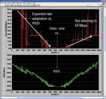
Figure 1 802.11g transmitter rate-adapting from 54 Mbps down to zero in response to diminishing signal strength. After the signal returns to its peak level, the adaptation algorithm is expected to recover the data rate of 54 Mbps, but does not.
Optimization and Test Challenges
It is extremely difficult for designers to test for and understand what is actually causing a particular Wi-Fi communication breakdown and how it is doing so. First, they must determine why throughput is dropping or the connection is being lost. Are too many devices placing demands at the same time, causing a bottleneck? Is there a lot of interference? Or both?
To complicate matters, there are two kinds of interference that adversely affect signal throughput and quality. Multipath refers to reflections in the environment that are created by the transmission itself, bouncing from various surfaces and taking multiple paths back to the same point. These paths have different associated time delays, causing the same information to arrive at different times, asynchronous to the main transmission.
The other kind of interference comes from seperate devices. The number of devices emitting in the unlicensed band dwarfs the number of 802.11 devices. These include, for example, microwave ovens, cordless phones, Bluetooth devices, wireless video cameras, outdoor microwave links, wireless game controllers, fluorescent lights and WiMAX. Even bad electrical connections can cause broad RF spectrum emissions. Non-802.11 types of interference typically don’t play well with 802.11 devices, and can cause a significant loss of throughput. What’s more, they can cause secondary effects such as rate back-off, in which retransmissions caused by interference “trick” the 802.11 devices into using lower data rates than appropriate.
Wireless designers tend to view these problems in terms of how the algorithms inside the device are responding and adapting to what is happening in the environment outside. The algorithms that control the Wi-Fi device use a variety of techniques to adapt to the changing signal environment. While these algorithms can offer significant improvements, there is still plenty of room for further optimization.
The illustration in Figure 1 provides more insight into the problem. In the top pane, a Wi-Fi transmission is humming along at a data rate of 54 Mbps when the received signal strength indicator (RSSI) starts dropping, possibly due to the motion of the two communicating radios away from one another. The RSSI is used to monitor the received signal strength in an IEEE 802.11 system and is basically an indication of the power level that is being received by the antenna.
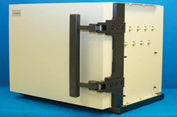
Figure 2 OctoScope octoBox – a small, anechoic RF isolation chamber.
As shown in the figure, the data rate drops to zero. Then, the RSSI starts increasing, possibly due to the radios moving closer together. The data rate recovers, via the data rate adaptation algorithm, but not completely. The data rate never recovers to its peak value of 54 Mbps, even though favorable channel conditions are restored. Meanwhile, the corresponding RSSI in the bottom pane provides no clue as to what is happening. In other words, the adaptation algorithms are inadequate for restoring the device back to its peak data rate. Finding out why and determining what to do is not easy.
One reason that the adaptation algorithms are difficult to optimize is that so many variables are in play (e.g., the statefulness of the algorithms and chipset to chipset interoperability) even in a controlled environment. When testing in open air, interference and multipath introduce even more variables into the mix, making it nearly impossible to determine what is happening and provide guidance to optimize the algorithms.
This is complicated by many different flavors of Wi-Fi that may be causing complex interactions. These must also be accounted for by the algorithms. For example, the set-top box might require 802.11ac while communicating with a router that only supports only 802.11n and a wireless headset that uses 802.11g. A headache, indeed.
To tackle the challenge of optimizing adaptation algorithms, designers must recreate the problem situations in order to see exactly what is impacting the signal and how the device is reacting. They need to emulate typical environmental conditions, including multipath and interference, and then reproduce the signal problem in a consistent fashion. With many variables in play and without a controlled environment, it is very hard to know what has happened and sort out potential causes. A controlled test environment is needed to perform the cycle of testing, tweaking of algorithms, testing and re-optimizing until the overall signal performance is fine-tuned.
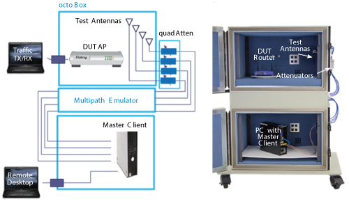
Figure 3 General configuration of stacked octoBox anechoic chambers with a wireless access point in the top chamber and a client device (a PC) in the bottom chamber.
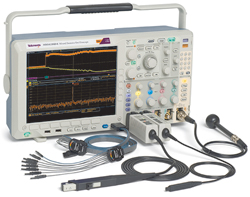
Figure 4 Tektronix's MDO4000B combines a spectrum analyzer with an oscilloscope and an RF input. It can also connect via live link to the SignalVu-PC vector signal analysis software package.
This is far easier said than done. Standard open air test labs are full of their own uncontrolled interference and are not very suitable as test environments. It is hard to create a clean, pristine area for measuring and debugging. One could spend millions of dollars to build a large isolation chamber, but that is not an option for many labs. Further, these types of problems are so time consuming to resolve that they can become a research project; for busy labs chamber time may be a limited resource.
Compact Anechoic RF Isolation Chambers
Fortunately, there are commercially available solutions. One approach is to use a set of small, RF isolation chambers as test beds, such as the one shown in Figure 2. These provide stable anechoic (echoless) conditions for over the air (OTA) signal transmissions inside. The master wireless access point can be put inside one chamber and the receiving device in another. They can be stacked one on top of the other and tethered together with a set of antennas. With the system sealed in a controlled environment, it can then be bombarded with typical interference and multipath by connecting a multipath emulator (MPE) or interference generator (signal library) to the system via another antenna.
A test system with two stacked anechoic chambers is shown in Figure 3. The chamber on top contains the wireless access point under test (e.g., a router). The chamber on the bottom contains the master client device (e.g., a PC tower). The stacked boxes are connected with a set of antennas, several programmable attenuators and an MPE. Extra antennas can be mounted to inject controlled interferences. The wireless link between the access point and the client device is established via the test antennas that couple the signal into the attenuators and then into the MPE. The attenuators model flat path loss caused, for example, by distance or walls. The MPE models the reflections from surfaces and walls in a typical house. This emulated but controlled environment presents realistic conditions that cause typical signal impairments in Wi-Fi networks.
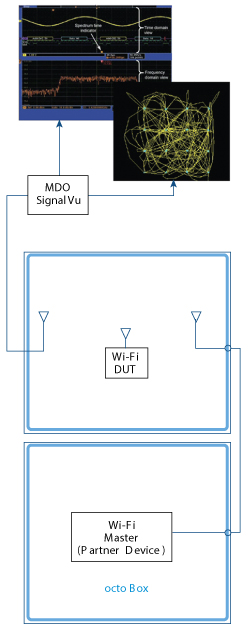
Figure 5 MDO4000B and SignalVu-PC vector analysis software connected via antenna to the DUT in the top of a set of anechoic chambers.
Signal Troubleshooting
Having created a controlled, sealed environment and emulated typical multipath and interference conditions, the problem can be reproduced in a consistent fashion, debugged and analyzed. Visualization and analysis tools are added to the mix in order to view what is happening while the device being tested is sending information to the client device and gain insight into the quality of the signal. For example, while the system is bombarded with interference and multipath, is it still receiving enough power so that it can actually operate?
One approach is to connect a spectrum analyzer, oscilloscope, arbitrary waveform generator and other signal analysis equipment to the anechoic chamber stack through various antennas. The drawback of this approach is that it is quite hard to isolate the problem without the ability to cross-reference the frequency domain with the digital domain (where the algorithms are produced). Combining a spectrum analyzer with an oscilloscope into one instrument is an effective solution. A mixed domain analyzer (MDO) such as the one pictured in Figure 4 includes a built-in RF input and wideband acquisition capability to capture the signals, as well as the ability to time-correlate the analog, digital and RF signals in a single instrument. Additionally, an advanced signal analysis capability can be provided via a live link from the MDO to vector signal analysis software running on a PC or laptop.
Using a set of anechoic chambers connected by antennas to an MDO and signal analysis software (see Figure 5), an event can be triggered (such as a sudden drop in throughput or unusual roaming behavior) in real time across frequency and time domains. These can be correlated to obtain a clearer picture of cause and effect: visualizing effects on functionality immediately on the RF side and correlating them to algorithms on the digital side.
The MDO’s spectral measurement and analysis capabilities (along with its connected signal analysis software) greatly simplify the process of making common transmitter measurements in a controlled environment. For example, you can create a spectral mask defined according to standards to check that the WLAN signal lies within this mask and view how clear and clean the spectral space is. You can do EVM measurements to look at the signal quality and compare it to a “golden reference.” Once you start injecting multipath and interference into the system, you can easily measure the adjacent channel leakage ratio (ACLR).
The use of portable, stacked anechoic chambers with multiple connecting antennas provides great flexibility in test configurations. For example, one antenna might be connected to an MDO, one to a multipath generator and the third and fourth to different kinds of interference, such as microwave or cell phone communication.
Conclusion
The clean, controlled test environment and analysis tools offered by a combined set of anechoic chambers and an MDO can help reduce the amount of time it takes to analyze WLAN signals and resolve problems without investing milllions. This solution can also be used for other applications, such as pre-compliance testing, where a clean test environment can put you ahead of the game.
Dorine Gurney has over 10 years of experience as a product planner at Tektronix. During her tenure she has supported multiple product lines including high performance oscilloscopes and more recently source/analyzer products and SignalVu solutions. Prior to Tektronix, Gurney worked as a product manager at Mentor Graphics. She has authored numerous application notes and technical articles and holds MSEE degrees from Rensslear Polytechnic Institute and Supélec.
Fanny Mlinarsky is the founder of octoScope, a wireless solutions and services company. Her background includes hands-on product development and R&D management. Prior to octoScope Mlinarsky was founder and CTO of Azimuth Systems, a wireless test equipment vendor. Mlinarsky has been an active contributor to the wireless standards being developed at 802.11 and 3GPP. She has published numerous articles, white papers and test reports on wireless topics.