
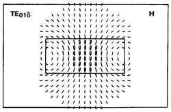
Figure 1 Magnetic field of TE01δ isolated dielectric resonator.
The widespread use of ceramic dielectric resonators in place of metallic resonant cavities in RF and microwave circuits started in the 1970s, with the first low loss, temperature stable barium tetratitanate ceramic materials.1 Further development of high dielectric constant ceramics with adjustable temperature coefficients enabled microwave engineers to use these materials in oscillator and narrowband filter designs for radar detectors, cellular phone and public safety base stations, satellite receivers and satellite broadcasting (TVRO/DBS) applications.
The most direct way of reducing the cost of microwave circuits is by reducing their size. The size of a dielectric resonator is considerably smaller than that of an air resonant cavity at the same frequency, because the relative dielectric constant of the material is substantially larger than unity, the dielectric constant of air. The resulting size reduction approximately equals the square root of the resonator’s dielectric constant,  . For example, a resonant circuit using a dielectric resonator with εr = 38 will be more than six times smaller than the equivalent air resonant cavity.
TE Mode Resonators
A dielectric resonator can be a short solid puck, cylindrical, tubular, spherical or even a parallelepiped shape. A commonly used resonant mode in cylindrical dielectric resonators is TE01δ. The magnetic field or dipole is shown in Figure 1, and the electric field consists of simple circles concentric with the axis of the cylinder is shown in Figure 2. Because of the high relative dielectric constant, a typical dielectric resonator stores more than 95 percent of its electric energy and over 60 percent of its magnetic energy in the TE01δ mode inside the cylinder. The remaining magnetic energy in the air around the cylinder decays rapidly with distance away from the resonator surface.
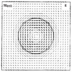
Figure 2 Electric field of TE01δ isolated dielectric resonator.
Choosing the ratio of the length of the resonator to its diameter to be in the range of 0.35 to 0.45 is most favorable because the fundamental resonant mode, TE01δ, exhibits a large enough frequency separation from other spurious modes, such as TM01δ.2 Mode separation can be accentuated by incorporating a concentric bore in the resonator cylinder where the electric field is weakest.
To a first order, the diameter of a cylindrical TE mode resonator at a resonant frequency F0 is given by

where Dr is the diameter of the resonator, εr is the dielectric constant of the resonator and c is the velocity of light. This assumes Dr ~2Lr, where Lr is the length of the resonator.
Although the resonant frequency of a dielectric resonator can be computed exactly by solving Maxwell’s equations, it is considerably more complex to compute the resonant frequency for a dielectric resonator mounted on microstrip or placed within a shielded metal cavity. The metal wall can affect the magnetic field and contributes to metal loss. When 0.35 Dr ≤Lr ≤0.45 Dr, the resonant frequency F0 (in GHz) of an isolated dielectric resonator in TE01δ mode can be calculated by

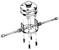
Figure 3 The Courtney holder for measuring dielectric constant.
where V is the volume of the dielectric resonator

Dr is the diameter of the dielectric resonator (in mm), and Lr is the length of the resonator (in mm).
The dielectric constant of the resonator can be measured to within 0.3 percent by using the parallel-plate procedure first introduced by Hakki and Coleman,3 assuming dimensional accuracies within ± 0.5 mils (± 127 µm) and frequency within ± 1 MHz. This method was later investigated for error analysis and temperature effects and is now commonly known as the Courtney method.4 Figure 3 shows the test fixture used for the measurements.
Circuit Integration
TE01δ mode dielectric resonators are generally magnetically coupled to the surrounding circuits. The most effective methods are bent coaxial probes or microstrip lines, as shown in Figure 4.
Metal cavities are usually used with resonator circuits because very high Q factors and accompanying narrow bandwidths can be obtained, and electromagnetic fields can be sustained within a lossless cavity at the resonant frequency. To eliminate conductor losses and environmental effects, shielding walls are best positioned away from the dielectric resonator, at a distance at least the radius of the resonator.
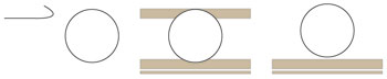
Figure 4 Methods for coupling to the dielectric resonator.
When a metal wall of a cavity is moved inward, the resonant frequency of the resonator will either decrease or increase, depending on whether the stored energy of the displaced field is predominantly electric or magnetic, respectively. Therefore, the resonant frequency must be fine-tuned. A screw mounted metal or dielectric plate can be used, or alternatively, a solid ceramic cylinder can be moved up and down between the shield cover wall and the dielectric resonator (see Figure 5). The gap created between the tuner and dielectric resonator (L2 in Figure 5) perturbs the fringe electromagnetic fields that exist outside the dielectric resonator. A metallic tuner approaching the dielectric resonator increases F0, and a dielectric tuner decreases F0. Up to 20 percent tuning can be achieved; however when using a metal tuner, the tuning range should be limited to only a few percent to avoid seriously degrading the Q factor and affecting the temperature coefficient of the dielectric resonator. The objective is to tune F0 while maintaining the same Q factor and temperature coefficient.

Figure 5 Tuning the frequency.
Typically, the outer and inner diameters of the dielectric resonator are kept constant within machining tolerances, and the length or thickness of the resonator is adjusted to compensate for small lot-to-lot and piece-to-piece F0 variations. Changing the diameter of the resonator or removing small quantities of ceramic from the resonator enable extremely tight F0 tolerances to be achieved, from ± 0.05 to ± 0.5 percent. A large resonator can be fine-tuned by attaching small tuning chips or pieces of ceramic material to the resonator using a low loss adhesive. The F0 can be lowered incrementally by adding various sizes or varying the position of the tuning chips; this approach achieves a tuning range of -1 to 2 percent.
Quality Factor
The figure of merit for assessing the performance or quality of a resonator is the quality factor, Q, which is a measure of the energy loss or dissipation per cycle compared to the energy stored in the fields of the resonator. The Q factor is defined by

where W0 is the stored energy, P is the power dissipation, ω0 is the resonant radian frequency and T is the period (2π/ω0). With a typical frequency response as shown in Figure 6, to a very good approximation, the loaded quality factor, QL, in a transmission curve is given by,

Figure 6 Relative transmission power as a function of frequency.

A cavity or resonator must deliver power to an external load in order to be useful.5 The loaded quality factor, QL, defines the overall power loss in a cavity or resonator system and includes both internal and external losses. The unloaded quality factor, Qu, accounts for the internal losses, and the external quality factor, Qe, accounts for external losses. The relationship between Qe, Qu and QL is given by

This shows that the smallest quality factor dominates. Hence, engineers using low loss dielectrics must consider the conductor and cavity structures to preserve the loaded Q factor in actual systems.
Qu is typically measured in a test cavity with dimensions that are at least two to three times the size of the dielectric resonator, to simulate an isolated and shielded resonator. A low loss, low εr material is used to support the resonator in the center of the fixture, and a bent coaxial probe is used for signal coupling. By employing such a test fixture with a dielectric resonator aspect ratio (Lr/Dr) in the range of 0.35 to 0.45, the F0, 3 dB bandwidth (Δf) and insertion loss (IL) can be measured using a network analyzer. Qu is then calculated using the equation

By eliminating the external loss Qe from the metal shielded wall, Qu just equals the dielectric resonator quality factor, Qd. Actual microwave circuits may have cavity dimensions only two times the size of the dielectric resonator or smaller. If the side wall or metal shield is close enough to the resonator, the TE resonant frequency will be affected by the size of the cavity and external loss will contribute to Qu. Including all contributors, the overall quality factor can be expressed as

where Qd is the quality factor of the dielectric resonator, Qc is the contribution from the metal wall, and Qr reflects losses from radiation. The first three terms on the right hand side of the equation make up the unloaded Qu factor of the resonant cavity:

When the shield is entirely closed and there is no radiation loss, the third term can be ignored.
Because conductor loss from the Courtney holder may contribute to the loss tangent (tan δ) measurement, some have estimated ± 40 percent error in tan δ. Kobayashi and Katoh6 proposed a clever way to remove the effect of conductor loss by using two different resonant modes, TE011 and TE01p, to obtain a much more accurate measurement. With a test cavity whose size is greater than twice the dielectric resonator and where the parallel plates are less than a half wavelength of air (λ0/2), the conductor and radiation loss terms can generally be removed. Then the unloaded Q factor is approximately equal to the dielectric Q factor, or Q = Qd.
Temperature Effects
The first temperature effect on the dielectric resonator is from thermal expansion, which is generally a small positive number. The physical dimensions increase with increasing temperature, resulting in a constant thermal coefficient of expansion, α, measured in ppm/°C. The relative dielectric constant, εr, also varies with temperature. As a first approximation, the change in εr is linearly proportional to temperature and can be represented by a constant, denoted by τε.
Therefore, the resonant frequency of a dielectric resonator will change with temperature from both the linear thermal expansion and the change in dielectric constant. The sensitivity of the resonant frequency to temperature changes, known as the temperature coefficient of resonant frequency, is given by the expression

By taking the appropriate derivatives of equation 10, we obtain

For cavities filled with inhomogeneous materials, equation 11 is modified to include a filling factor, Pe, to account for the surrounding environment.

Pe can be very close to unity for homogeneous cavities and less than unity for inhomogeneous cavities.
Depending upon the size and proximity of the cavity to the dielectric resonator, the thermal expansion of the cavity may contribute a substantial amount to the temperature coefficient of the dielectric constant τε, leading to a discrepancy between the calculations and the actual τε in the design.7 For best results, τε should be measured, generally between 20 and 120°C is sufficient to determine the linear relationship.
Commercial High Q Dielectric Resonator Materials
Early resonators with dielectric constants near 36 were based on barium polytitanates and Zr(Ti,Sn)O4. Ultimately, resonators evolved to higher Q, low τf crystalline phases having more complex chemistries, fabricated with materials in the BaO −TiO2 −ZnO −Nb2O5/Ta2O5 and ZrO2 – TiO2 – ZnO −Nb2O5 systems. Perovskite compounds incorporating Nd2O3, TiO2 and CaO/SrO or BaO, ZnO, CoO and Nb2O5 are also used.8 Such resonators have dielectric constants from 34 to 47 and with typical
Q X f0 values of 40,000 to 70,000, when measured between 5 and 6 GHz.
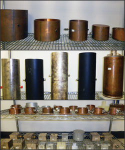
Figure 7 Custom resonator test cavities.
Super high Q resonators with dielectric constants near 30 and 24 are now commercially available. Ultra high Q X f0 values range from 100,000 to 300,000 can be obtained when measured near 10 GHz. These are based on perovskite compounds incorporating BaO, MgO, ZnO and Ta2O5, with additives to control and vary τf. These super high Q resonators are primarily used for dielectric resonator oscillators (DRO) at Ku and K-Band. Precise mechanical dimensions and very tight tolerance in εr (± 0.5) and τf (0.5 percent) are required for K-Band DRO applications. Unlike the first group of dielectric resonators, to maintain the extremely tight tolerances in electrical properties and Q values, super high Q resonators require much more experience in dielectric materials research and development as well as expertise in powder processing and manufacturing technology.
Conclusion
Successful utilization of high Q dielectric resonators in resonant cavities relies on precision control of the raw materials, recipes, powder processing, manufacturing and custom adjustment in actual applications. Consistent lot-to-lot and piece-to-piece resonator performance ensures successful designs and high yield production. Understanding how boundary conditions affect the resonant frequency, dielectric constant, quality factor and the temperature coefficient of resonant frequency is important to both resonator cavity design engineers and material manufacturers. Having a wide range of custom test cavities, as shown in Figure 7, enables correlated testing to ensure resonator performance in actual applications.
References
- J. K. Plourde, H. M. O’Bryan, Jr., D.F. Linn, H. and J. Thomson, Jr., “Ba2Ti9O20 as a Microwave Dielectric Resonator,” Journal of the American Ceramic Society, Vol. 58, pp. 418-420, Sept.-Oct. 1975.
- K. A. Zaki, C. Chen and A. E. Atia, “Canonical and Longitudinal Dual-Mode Dielectric Resonator Filters Without Iris,” IEEE Transactions on Microwave Theory and Techniques, Vol. MTT-35, pp. 1130-1135.
- B. W. Hakki and P.D. Coleman, “A Dielectric Resonator Method of Measuring Inductive Capacities in the Millimeter Range,” IRE Transactions on Microwave Theory and Techniques, Vol. MTT-8, pp. 402-410, July 1960.
- W. E. Courtney, “Analysis and Evaluation of a Method of Measuring the Complex Permittivity and Permeability of Microwave Insulators,” IEEE Transactions on Microwave Theory and Techniques, Vol. MTT-18, pp. 476-485, August 1970.
- G. L. Matthaei, L. Young and E. M. T. Jones, “Microwave Filters, Impedance-Matching Networks and Coupling Structures,” Artech House, 1980, ISBN 0-89006-099-1.
- Y. Kobayashi and M. Katoh, “Microwave Measurement of Dielectric Properties of Low-Loss Materials by the Dielectric Rod Resonator Method,” IEEE Transactions on Microwave Theory and Techniques, Vol. MTT-33, pp. 586-592, July 1985.
- D. Kajfez and P. Guillon, “Dielectric Resonators,” 2nd Edition, SciTech Publishing, 1998, ISBN 1-884932-05-3.
- T. Negas, G. Yeager, S. Bell and N. Coats, “BaTi4O9/Ba2Ti9O20-Based Ceramics Resurrected for Modern Microwave Applications,” American Ceramic Society Bulletin, Vol. 72, pp. 80-89, 1993.