
One of the requirements driving innovation in today’s RF signal analyzers is the constant push for wider instantaneous bandwidth. From radar systems to spectrum monitoring to the next generation of wireless communications, engineers require more measurement bandwidth to analyze evolving types of signals. Although the design and manufacturing of extremely wide bandwidth RF signal analyzers was once cost-prohibitive, the increasing performance of off-the-shelf, analog-to-digital converters and advanced signal processing technologies like LabVIEW FPGA has allowed National Instruments to develop the widest bandwidth high performance RF signal analyzer currently on the market – the PXIe-5668R.
This RF signal analyzer offers 765 MHz of instantaneous bandwidth without compromising measurement speed or analog performance. The wide bandwidth of this high performance microwave signal analyzer is able to address applications such as radar test and spectrum monitoring – but with the dynamic range required for RFIC characterization and low-level spur sweeps.
One unique feature of this PXI signal analyzer is the inclusion of an onboard LabVIEW-programmable FPGA. By programming its Xilinx Kintex-7 FPGA, engineers are able to customize the behavior of the instrument by adding in-line signal processing routines or real-time control of a device under test.
Architecture
The PXIe-5668R uses two distinct signal paths to deliver a combination of wide instantaneous bandwidth and best-in-class RF performance. In the low-band path below 3.6 GHz, the instrument uses a three-stage superheterodyne design with optional pre-amplification. In the high-band path, above 3.6 GHz, the instrument uses a two-stage design with a yttrium-iron-garnet (YIG)-tuned filter (YTF) for pre-selection.

Figure 1 Simplified block diagram of PXIe-5668R.
In the low band of the PXIe-5668R (below 3.6 GHz), the instrument contains several features to improve measurement performance. Figure 1 highlights a simplified block diagram. Notice that the 30 dB preamplifier can be engaged to reduce the instrument’s inherent noise floor when measuring low-level signals.
Figure 1 also illustrates two high-pass filters before the first mixing stage. Engineers can engage these filters with a high-pass cutoff of 1350 and 2200 MHz to suppress fundamental frequency of common cellular communications bands around 1 GHz. With filters enabled, the instrument can more accurately measure second and third harmonics of devices, such as a power amplifier at approximately 2 and 3 GHz, respectively.
In the high band, above 3.6 GHz, a YTF function as a pre-selector for operation from 3.6 to 26.5 GHz, which is enabled by default for spectrum measurements. For extremely wideband vector signal analysis, one can disable the YTF to utilize the full 765 MHz of instrument bandwidth.
In conjunction with a 2 GSa/s digitizer sample rate, the VSA’s downconverter has a flexible IF structure that allows both high-end spectrum analysis and wideband vector signal analysis. For example, a narrow 300 kHz analog filter can be engaged to facilitate measurements requiring the highest dynamic range, such as two-tone intermodulation distortion (IMD) or ACLR. For vector signal analysis, the IF filtering can be entirely disabled to allow for bandwidths of up to either 320 or 765 MHz, depending on the center frequency.
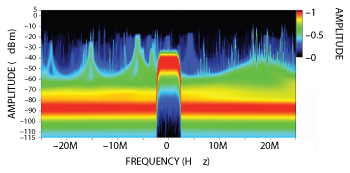
Figure 2 The real-time spectrum analysis capability of the PXIe-5668R enables visualization tools such as the persistence display.
Radar Design and Test
Engineers tasked with the design and test of advanced radar systems are utilizing increasingly wider signal bandwidths. In fact, typical radar signals such as the pulsed or modulated transmissions often require signal bandwidth that is much wider than what traditional RF signal analyzers can measure in a single acquisition.
In pulsed radar applications, fast switching pulsed signals produce extremely wide bandwidths. In order to accurately perform measurements such as rise-time, fall-time and pulse width, one must capture the full bandwidth of the signal – which includes a main lobe and several side lobes. Moreover, statistical properties of the pulse measurements, such as standard deviation, improve with increased bandwidth of the signal analyzer.
Historically, radar circuit designers have used the relationship “bandwidth = 0.35/pulse rise time” to determine the minimum bandwidth requirements of the radar receiver. This rule of thumb was to ensure that the bandwidth is sufficient for the rise time portion of the pulse to pass through the analog front end of the instrument without significant distortion. However, accurate measurement of radar pulse requires even wider bandwidth from the instrument. A general rule for performing advanced measurements on a pulse with rise time of x nanoseconds is that the VSA’s instantaneous bandwidth must be 3/x. For example, to measure pulse rise times as low as 5 ns, the recommended instrument instantaneous bandwidth would be 3/(5 ns) or 600 MHz.
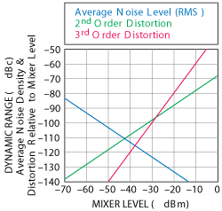
Figure 3 PXIe-5668R dynamic range chart at 20 GHz.
A second radar application that uses wide bandwidth is the use of Linear Frequency Modulated (LFM) Radar or Chirp Radars. In order to resolve two targets in space, radar engineers ideally need progressively narrow pulses. However, the amount of power one needs to generate on the target to get dissent distance/return is directly related to transmitted power. As the pulses get narrow (to gain resolution), engineers either have to generate unpractical peak power narrow pulses or give up range. LFM is an elegant answer to this problem and is a very similar concept to spread spectrum techniques in radios.
Spectrum Monitoring Signal Intelligence
Another application that requires wide bandwidth measurement capabilities is spectrum monitoring and signal intelligence. In these applications, wide instantaneous bandwidth allows engineers to monitor multiple transmissions simultaneously with a single instrument. Using the onboard FPGA, the PXIe-5668R signal analyzer is able to perform real-time spectrum analysis without gaps in the time-domain record (see Figure 2).
Real-time spectrum analysis allows engineers to analyze and view the most elusive signals. Such gap free spectral analysis is achieved through the use of a high performance FPGA computing up to 2 million overlapping FFT’s per second. Spectral data is then visualized using both persistence and spectrogram displays.
Analog Performance
In addition to extremely wide bandwidth, the analog performance of the PXIe-5668R enables engineers to more accurately perform a wide range of RF measurements. In fact, the combination of low phase noise, low noise floor and high second and third order intercepts provides excellent dynamic range for applications ranging from adjacent channel leakage ratio (ACLR) measurements to spurs and harmonics measurements.
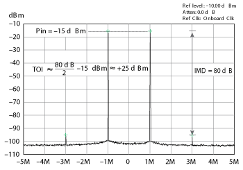
Figure 4 PXIe-5668R Intermodulation Distortion Measurements.
The dynamic range chart in Figure 3 illustrates both the instruments’ noise and linearity as a function of mixer level. The signal analyzer achieves an SFDR of up to 115 dB of SFDR in 1 Hz of bandwidth at 20 GHz.
IMD and ACP Measurements
A combination of a highly linear front end and low noise are critical for engineers performing measurements such as intermodulation distortion (IMD) and adjacent channel power (ACP). In fact, the specification that best represents the ability of an instrument to perform these measurements is third-order intercept (TOI). The PXIe-5668R has a TOI specification of better than +23 dBm at 1 GHz with 0 dB of attenuation. As Figure 4 illustrates, the instrument delivers nominal TOI performance of +25 dBm at 1 GHz.
Although the TOI specification of an RF signal analyzer is defined using 0 dB of attenuation by convention, an RF signal analyzer can measure TOI much higher than its specification. In practice, you can optimize measurement system linearity by switching the instrument’s internal attenuation on the PXIe-5668R.
In addition to IMD measurements, the high dynamic range of the PXIe-5668R makes it ideal for spectrum measurements such as ACP and the related measurement, Adjacent Channel Leakage Ratio (ACLR). Figure 5 illustrates an ACLR measurement of a
W-CDMA signal and shows an inherent ACLR floor of approximately 85 dB.
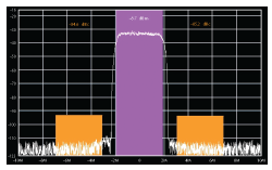
Figure 5 PXIe-5668R W-CDMA ACLR performance at 468 MHz.
NI wireless standards software toolkits software allows the PXIe-5668R to test devices using technologies including GSM/EDGE, UMTS/HSPA+, LTE/LTE Advanced, Bluetooth and 802.11a/b/g/n/p/ac.
Multi-Channel Analysis
As a result of this instrument’s modular architecture, additional downconverter and digitizer modules support multichannel receiver configurations. The PXIe-5668R VSA provides the ability to share the local oscillator and other timing signals across multiple modules and allows for phase-coherence between each RF channel. The phase-coherence of multichannel receivers is important in applications ranging from direction finding to beamforming and multiple input, multiple output (MIMO) device testing.
The PXIe-5668R is a high-performance 26.5 GHz VSA that is ideal for a wide range of applications. The combination of extremely wide bandwidth, excellent analog performance and ultimate flexibility empowers customers to solve challenging measurement applications ranging from ACLR measurements to radar verification and spectrum monitoring.
National Instruments
Austin, Texas
www.ni.com/microwave