
An RF front end device called the Transmit Isolating Receiver (TIRx) takes the place of both a circulator and low noise amplifier in a conventional RF front end, enabling full-duplex wireless communication by transmitting and receiving simultaneously on the same frequency through a single antenna. The TIRx RF front end enables single channel full duplex communications by providing a high degree of T/R isolation, exceeding 40 dB over four decades of bandwidth. When combined with appropriate digital interference cancellation, systems delivered with the TIRx RF front end have achieved >80 dB of T/R isolation over multiple frequency bands even when connected to an antenna with poor return loss.
Wireless services are expanding exponentially with more and more users demanding ever-wider bandwidth. At the same time, the RF spectrum supporting these services is constrained by market forces and government regulations. Acquisition of additional spectrum involves huge capital expenditures for its purchase, infrastructure installation and support.
Within current spectrum allocations, the frequency channels for various services are either separated to avoid interference or are further subdivided into separate uplink and downlink sub-channels. This results in an inefficient utilization of RF spectrum that could be alleviated with simultaneous transmit and receive (STAR) on the same frequency channel, also known as full-duplex operation. Potentially, such full-duplex operation could more than double the capacity of current wireless systems. It could also help solve important problems with current networked systems that affect the Quality of Experience (QoE) and provide future opportunities for new enhanced services.
The key challenge to implementing STAR is protecting the receiver from the high powered transmit signal to a sufficient degree; the figure of merit that quantifies the degree of protection is known as transmit-to-receive (T/R) isolation. The T/R isolation required is dictated largely by the transmit power and the receiver noise level, and varies from a minimum of about 40 dB to well over 100 dB for various applications. For example, as noted by Choi et al.,1 IEEE 802.15.4 personal area networks (e.g., ZigBee) use 0 dBm transmit power and the noise floor in the receiver is around -100 dBm. Thus, as much as 100 dB of T/R isolation within the device is required in such networks to avoid self-interference.
Since many of today’s wireless devices have multiple antennas to support multiple input, multiple output (MIMO) processing, one possible way to achieve isolation is to use separate antennas for transmit and receive. Within small devices such as tablets and phones, only a few centimeters of separation is possible, making it difficult to achieve the significant T/R isolation required. Also, for many applications, it is desirable to use the same antenna for both transmit and receive to maximize system flexibility and performance and minimize cost.
If the same antenna carries both transmit and receive signals on the same frequency channel, the conventional approach is to use an RF circulator instead of a frequency diplexer to separate them. Unfortunately, conventional RF circulators based on the use of ferroelectric elements can achieve only about 20 dB of isolation over an octave bandwidth. Much deeper isolation nulls are available, but these cover only a narrow bandwidth. Active electronic circulators have been developed, but their isolation versus bandwidth performance is about the same, and they cannot withstand high transmit signal powers.
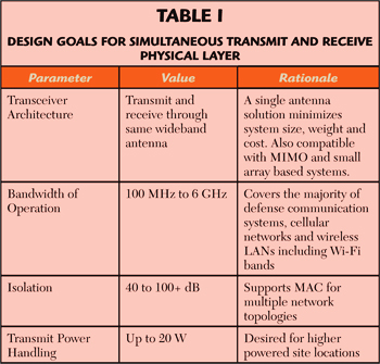
Photonic Systems Inc. (PSI) has been investigating this full-duplexing problem for both defense and commercial wireless applications in order to develop a physical layer (PHY) solution applicable to a wide range of wireless networks and devices, as shown in Table 1. A major goal of this development is a transceiver architecture that is broadband without requiring separate transmit and receive antennas. This would exploit all the benefits of MIMO systems and provide the most degrees of freedom for the receiver’s digital signal processing, thus maximizing spectrum utilization and network performance. Achieving broad bandwidth depends upon the availability of a wideband antenna, but this architecture could also be used with, or retrofitted into, installations with narrowband antennas.
A high degree of isolation – at least 40 dB to satisfy initial needs, but ideally 80 dB or more – is desired to support a broad range of media access control (MAC) topologies. A goal of up to 2 W transmit power works with many types of cellular and Wi-Fi installations. An additional goal not stated in Table 1 is to provide a solution whose cost is consistent with existing economic models for wireless services.
DESIGN CONCEPT
Most RF circulators work by summing and differencing the RF phase of two waves travelling in opposite directions around the circumference of a ferrite disc. The isolation is achieved by the constructive interference between the two waves at one port of the device and destructive interference at the other port. This approach is inherently narrowband, resulting in bandwidths appreciably less than an octave, although some broader-band circulators have been developed by sacrificing isolation.
In contrast to ferrite-based RF circulators, the approach described here leverages photonics to extend both bandwidth and isolation simultaneously, as illustrated in Figure 1. One might think of this as a photonic circulator, but in addition to achieving the functionality of an RF circulator, it also provides receive signal gain with a low noise figure like an RF low noise amplifier (LNA). It is, therefore, more appropriately called a transmit-isolating receiver RF front end, or TIRx.2
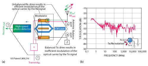
Figure 1 TIRx theory of operation (a), and measured T/R isolation (b).
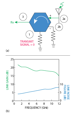
Figure 2 TIRx connection for receive functions (a); measured gain and noise figure (b).
Figure 1a illustrates the operational principle. To achieve broad-bandwidth isolation, a balanced drive optical Mach-Zehnder modulator is used.3 In a balanced drive modulator, applying the same signal to both electrodes results in the same optical phase modulation being applied to each arm. When the two arms recombine (as shown in blue), the result is – at least ideally – no intensity modulation of the optical carrier. To implement a TIRx, the transmit signal is applied to both of the TIRx drive ports, resulting in no modulation of the CW laser light. Thus, as desired, the transmit signal travels along the modulator electrodes directly to the antenna but is not conveyed to the TIRx receive output port. The receive signal from the antenna, however, is applied to only one of the modulator’s electrodes, resulting in efficient unbalanced modulation of the optical carrier. The resulting optical modulation is detected at the receive port of the TIRx.
Since balanced drive operation extends “from DC to daylight,” this is – in principle – a mechanism for achieving high isolation over an extremely broad bandwidth. Figure 1b is a plot of the measured T/R isolation versus frequency for a TIRx showing >40 dB of isolation over four decades of bandwidth with a 50 ohm load in place of the antenna.
As shown in Figure 2a, the TIRx has only RF input and output ports, but inside it contains a complete RF photonic link. The photonic components include a CW laser, an optical modulator and a photodetector. While previous photonic links had high noise figures (typically >20 dB) and high insertion loss, photonic links with low noise figures and positive link gain have been recently demonstrated (see Figure 2b).4 This illustrates the second function of a TIRx: its receive path has RF power gain and a low noise figure (like an electronic LNA). In the wireless service bands between 700 MHz and 6 GHz, the measured data in Figure 2b show the noise figure varying from 4 to 6 dB and the gain from 17 to 21 dB. These are useful values for most wireless network applications.
Since the transmit signal passes through the device, it is important to quantify its power handling capability. The current carrying capability of the electrodes of the optical modulator limits the power handling of the device. Present optical modulators have been shown to withstand 20 W (43 dBm) of transmit power through typical TIRx devices.
Compared to ferrite-based RF circulators, the TIRx has much higher T/R isolation over much greater bandwidth; however, when either device is terminated in 50 ohms, partial reflection of the transmit signal by an actual (not perfectly 50 ohm) antenna at the bi-directional port back into the receiver path will degrade the isolation across a broad bandwidth. It is theoretically possible to counteract this effect by improving the impedance match to the antenna, but it is physically unrealizable to achieve the required combination of bandwidth and antenna return loss improvement required to meet the STAR requirements in Table 1 because such a combination of bandwidth and impedance match exceeds the Bode-Fano limit.5
The TIRx has a different way of addressing this issue via the fourth port as shown in Figures 1a and 2a. The approach is to connect a variable impedance to this port that replicates the antenna impedance versus frequency. Unlike impedance-matching that attempts to transform one impedance to another, and is bandwidth-limited per Bode-Fano, there is no limit to the degree that one impedance can replicate another. This “Antenna Balance” port balances out the impedance variation of the antenna. With reference to Figure 1a, at any frequency where the impedance presented at the two bidirectional ports are equal, the transmit signal at Port 1 is routed to the antenna connected to Port 2, and the signal received by the antenna is routed to Port 3. But Port 3 is substantially isolated from Port 1 because even the portion of the transmit signal that is reflected by the antenna back into Port 2a is exactly balanced by the portion of the transmit signal reflected back into the “balance” Port 2b by the impedance that is connected to the fourth port. Therefore, the front end will have excellent T/R isolation. This is one important feature of the TIRx that distinguishes it from conventional ferrite circulators.
By itself, the analog cancellation capability of the TIRx is not enough to achieve the isolation goals in Table 1 mainly due to limitations of the optical modulator and differences between the antenna impedances and the balance. If, however, the analog front end suppresses the transmit signal in the receive channel to a degree that will sufficiently ensure linearity in that signal path, digital signal cancellation can further improve the T/R isolation. In digital cancellation, an estimate of the interfering signal is subtracted from the received signal in the digital domain. Since the transceiver “knows” the signal it is transmitting, a good (but not a perfect) estimate of the interference is available.
PROOF OF CONCEPT DEMONSTRATION
Figure 3 shows a block diagram of a two-channel proof-of-concept demonstration system requiring 40 dB of T/R isolation in a 1 MHz to 6 GHz bandwidth. The system consists of a pair of customer-supplied broadband antennas, two TIRx front ends and a pair of signal processing boards. The CW laser for the optical modulator is located remotely from the antenna via about 150 feet of polarization-maintaining (PM) fiber. Similarly, the signal received by each antenna is carried to the signal processing boards over a single-mode fiber. Two copies of the transmit signal, necessary for STAR operation of the TIRx, are supplied to each antenna interface unit over coaxial cable.

Figure 3 Block diagram of the proof-of-concept, full duplex, demonstration system.
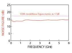
Figure 4 Plot of demonstration system STAR-mode noise figure versus frequency.
The system is assessed for a large number of performance parameters, a few of which are discussed. One of the important STAR parameters is receive noise figure versus frequency, a plot of which is shown in Figure 4. The broad bandwidth capability of photonics is evident in this plot, which shows a relatively constant noise figure less than 15 dB over the entire frequency range of 1 MHz to 6 GHz. It is important to note that in STAR-mode there is no electronic LNA; the TIRx is connected directly to the antenna element. The noise figure, however, is higher than might be desired for demanding applications. As shown in Figure 2b, lower noise figures have been demonstrated using more sensitive modulators.
Another important receive parameter is the spurious-free dynamic range (SFDR). In STAR operation, there is a potential for intermodulation products to be generated between transmit and receive signals in addition to intermodulation products generated between two receive signals. For the demonstrated system, the receive-channel SFDR in the absence of a transmit signal is 113 dB·Hz2,3. The SFDR limited by mixing with the strong (2 W) transmit signal is ≥ 42 dB, as shown in Figure 5.
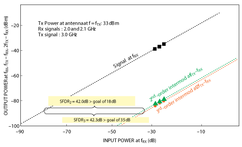
Figure 5 Plot of 2nd and 3rd order SFDR versus receive power for a transmit power of 2 W.
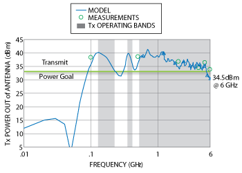
Figure 6 Plot of transmit power from the antenna versus frequency.
One aspect of Tx-Rx intermodulation is that both have a slope of 1, unlike Rx-Rx intermodulation with slopes of 2 and 3, respectively. To understand the basis for this difference, consider the following: in the case of receive-receive SFDR, the strongest second-order intermodulation products are fRX1 - fRX2, fRX2 - fRX1, and fRX1 + fRX2, and the strongest third-order intermodulation products are 2 fRX1 - fRX2 and 2 fRX2 - fRX1. In the case of transmit-receive SFDR the strongest second- and third-order intermodulation products are, respectively, fTX1or2 ± fRX1or2 and 2 fTX1or2 - fRX1or2. One can see that the receive frequencies appear twice or thrice in each of the intermodulation products that determine, respectively, the second- and third-order receive-receive SFDR, whereas they appear only once in each of the intermodulation products that determine transmit-receive SFDR. Therefore, in a plot of transmit-receive SFDR, the second- and third-order intermodulation distortion products both have a slope of 1 (see Figure 5).
In the STAR transmit path, an important parameter is the transmit power because the RF transmit signal passes through the TIRx along the modulator’s electrodes. For the demonstration system, the application goal is 2 W of power transmitted from the antenna at any frequency where the antenna return loss is less than 7 dB. Applying this constraint results in the bands shown in Figure 6, a plot of transmit power from the antenna versus frequency. It is interesting to note that achieving transmitted power of 2 W from an antenna with a return loss of 7 dB corresponds to 0.5 W of transmit power reflected back into the receive path. Modeled and measured results show ≥34.5 dBm out of the antenna from 500 MHz to 6 GHz, exceeding the goal.
The key STAR parameter is T/R isolation. As noted earlier, the system shown in Figure 3 employs a two-step approach to achieve high isolation over a wide bandwidth when transmitting and receiving simultaneously via a single antenna. The first step takes advantage of high TIRx isolation. This reduces the linearity requirement on the subsequent components in the receive path by suppressing the large transmit signal before it encounters any nonlinear component. The second step employs signal processing to further suppress the residual transmit signal from the receive path. The results of applying this two-step approach are the plots in Figure 7, which show measured T/R isolation at the signal processor output. The isolation is > 70 dB in both channels from 200 MHz to 3 GHz and > 80 dB in one of the channels up to 1 GHz. The isolation decreases above 3 GHz, but the minimum isolation of 54.9 dB at 5 GHz in one of the channels still easily exceeds the system’s requirement of
> 40 dB.
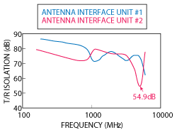
Figure 7 Plot of T/R isolation versus frequency at the output of the signal processor.
For applications requiring greater T/R isolation, further improvements can be made. It should be noted that the T/R results in Figure 7 are obtained with the TIRx connected to a customer provided antenna that has wide bandwidth, but a return loss of only 7 dB at some frequencies. Connecting an impedance that replicates this antenna’s impedance to the antenna balance port on the TIRx enables roughly 20 dB of the T/R isolation to be achieved in the analog front end, placing the remainder of the burden on the signal processing. An important consequence of this is that the instantaneous bandwidth (IBW) over which the transmit signal is suppressed becomes dependent on the IBW of the signal processing hardware – e.g., the A/D converters and FPGA. In contrast, the IBW of the T/R isolation at the output of the TIRx itself is the full TIRx operating bandwidth, shown by the data plotted in Figure 1b, that will extend over decades.
CONCLUSION
This article describes technologies that enable full-duplex wireless communication by transmitting and receiving simultaneously on the same frequency through a single antenna. The key enabler is a unique RF front end device called the Transmit Isolating Receiver (TIRx) that takes the place of both a circulator and low noise amplifier in a conventional radio RF front end. The TIRx RF front end enables single channel full duplex communications by providing a high degree of T/R isolation, exceeding 40 dB over four decades of bandwidth. This covers the majority of defense, land mobile radio, cellular and wireless network communication frequency bands. When combined with appropriate digital interference cancellation, systems delivered with the TIRx RF front end have achieved >80 dB of T/R isolation over multiple frequency bands even when connected to an antenna with poor return loss. This new RF front end technology could effectively double the spectral efficiency of any wireless network.
ACKNOWLEDGMENT
Some of the work described in this article was supported by DARPA under SSC-San Diego Contract N66001-04-C-8045. The views and conclusions contained in this article are those of the authors and should not be interpreted as representing the official policies, either expressed or implied, of the DARPA or SSC-San Diego.
References
- J.I. Choi, M. Jain, K. Srinivasan, P. Levis and S. Katti, “Achieving Single Channel, Full Duplex Wireless Communication,” Proceedings of the Sixteenth Annual International Conference on Mobile Computing and Networking, September 2010, pp. 1–12.
- C. Cox, “Bi-Directional Signal Interface and Apparatus Using Same,” U.S. Patent 7,809,216, October 5, 2010.
- C. Cox, Analog Optical Links, Cambridge University Press, New York, 2004, Section 2.2.2.1.
- H. Roussell, M. Regan, J. Prince, C. Cox, J. Chen, W. Burns, E. Ackerman, and J. Campbell, “Gain, Noise Figure, and Bandwidth-Limited Dynamic Range of a Low-Biased External Modulation Link,” Proceedings of the IEEE International Topical Meeting on Microwave Photonics, October 2007, pp. 84-87.
- R.M. Fano, “Theoretical Limitations on the Broadband Matching of Arbitrary Impedances,” Technical Report No. 41, Massachusetts Institute of Technology, Research Laboratory of Electronics, January 1948.
Charles H. Cox III, is the president and CEO of Photonic Systems Inc. (PSI). Prior to founding PSI, Cox was on the research staff at MIT and at Lincoln Laboratory; he received his ScD from MIT. Cox holds 10 U.S. patents, has given three plenary and 71 invited talks on RF/microwave photonics and has published more than 70 papers on his research in the field. He has written a textbook titled “Analog Optical Links,” co-edited a book on milestone papers in photonics and written five book chapters. He is a fellow of IEEE and OSA. Cox served as a member of the Advisory Group on Electron Devices (AGED) from 2003 – 2009.
Edward I. Ackerman is vice president of research & development at Photonic Systems, Inc. (PSI). In addition to PSI, Ackerman’s technology and product development experience includes work at GE Electronics Laboratory and MIT Lincoln Laboratory. Ackerman has co-edited a book and has authored or co-authored three book chapters as well as more than 50 technical papers on the subject of RF/microwave photonic subsystem performance modeling and optimization. Ackerman is a Fellow of the IEEE and holds seven U.S. patents.