
Precise cross-element phase and magnitude measurements and increased measurement bandwidth and system flexibility dramatically speed up large antenna array calibration
The market for multi-channel, phased-array antennas is growing and bringing increased pressure on manufacturers to reduce costs and increase test capacity. At the same time, manufacturers of these antennas need to expand test system flexibility to cover broad use cases and provide options for future upgrades, while facing multi-channel phased array antenna calibration and test challenges including:
- An increase in test times and test complexity due to a growing number of array elements
- Phase coherent sampling across all input channels, providing relative amplitude and phase measurements is critical for precise beamforming
- Advancements in antenna and radar technologies require a flexible and upgradeable test system
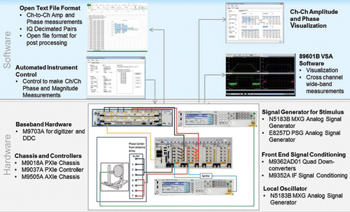
Figure 1 MAC block diagram.
The multi-channel antenna test Reference Solution, the second in a series of modular-based Reference Solutions introduced by Keysight Technologies earlier this year, is a combination of hardware, software, and measurement expertise providing the essential components of a narrow-band antenna calibration test system. With this Reference Solution, engineers have the ability to meet antenna test and calibration challenges with a new test approach and enhance or modify a test system to meet specific test application requirements. They include scalable channel count, options for downconversion of antenna receive channels, selectable analysis BW and choice of RF/microwave sources and LO. The Reference Solution also allows a test system to be extended to wide-band measurements as needs change.
To facilitate evaluation and integration in a test environment the Reference Solution provides test code examples to set up receiver channels, including DDC, make phase and magnitude measurements, add channel-channel correction factors and export measurements for post-processing.
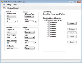
Figure 2 Test setup and control.
Reference Solution Architecture
Antenna Calibration Example Software
This Reference Solution contains a C# test code example, specifically designed to collect data from an antenna under test and compute cross-channel magnitude and phase data. To accelerate test development and facilitate integration into a test environment, example software source code is provided in the form of a .NET class library. This allows the example to be built-upon (using Microsoft Visual Studio or National Instruments LabVIEW) and the collection and processing of data is customized for specific application needs. The Reference Solution antenna calibration example software provides a number of unique features and capabilities that facilitate and speed calibration and testing, including test setup and control, utility and file functions, cross-channel measurement computation, and measurement interval isolation (see Figure 1).
Test Setup And Control
The Reference Solution’s example GUI allows users to set up the measurements made with the M9703A digitizer, including control over DDC parameters (see Figure 2). It includes settings such as initial sample rate, number of samples/segments, trigger control and decimated IQ sample rate. It also allows the user to select which digitizer channels are used for the test and the reference channel for cross-channel measurements. Once the test conditions are set the hardware is configured, data is acquired, and the decimated I-Q data record is uploaded to the host computer (see Figures 3 and 4).
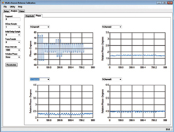
Figure 3 Cross-channel phase measurements for all I-Q samples with absolute (reference channel) and relative (other channels) values.
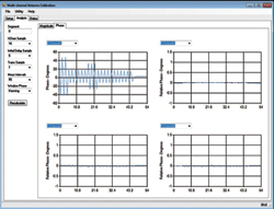
Figure 4 Absolute and relative phase plots, after computing a single I-Q pair for each interval and applying a calibration table.
Computing Cross-Channel Measurements
The analysis tab allows quick visualization of absolute or relative phase/magnitude measurements for all measurement intervals in a selected segment.
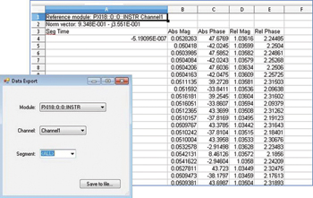
Figure 5 Exporting cross-channel I-Q measurement.
Isolating Measurement Intervals
The analysis tab also allows measurement intervals to be isolated by selecting the number of samples to integrate over and setting the interval delay and transition time (samples) between intervals. After recalculating, the software will generate a single I-Q measurement for each interval. Again, the plots can be used to visualize either relative or absolute measurements (see Figure 4).
Utility and File Functions
The example software also has utility and file functions to help improve and utilize test results. For example, a cal table containing channel-channel magnitude/phase correction factors can be loaded for use when calculating the cross-channel measurements (see Figure 5).
Conclusion
The Keysight multi-channel antenna calibration Reference Solution provides antenna manufacturers greater testing flexibility for more applications and can be quickly integrated into a receiver channel calibration test environment, using near-field, narrow-band testing of the array. The solution allows antenna manufacturers to meet the demand for reduced costs and increased test capacity by making more antenna measurements per second; measuring multiple, phase-coherent channels in parallel; and optimizing the amount of data though real-time digital down-conversion (DDC).
Keysight Technologies Inc.
Santa Rosa, Calif.
www.keysight.com/find/solution-mac