
Radiation is a proven therapy for treating cancer. However, targeting a radiation beam on organs that move — such as cancers located in the liver, stomach or lungs — can be challenging, especially when the images used to locate a tumor are days, or even weeks, old. Researchers at the Cross Cancer Institute in Edmonton, Canada are using simulation to model the complicated RF fields involved in the process to develop a system in which a tumor can be both imaged and treated simultaneously.
Ever since the benefits of using radiation for treating cancer were first discovered, the challenge has been how to maximize damage to cancerous cells, while simultaneously minimizing the destruction of surrounding healthy tissues and organs. While attempts at leveraging this therapeutic index have led to the advent of a variety of innovative approaches, a central problem still remains — how to accurately determine a tumor’s size, shape, location and position in time, and utilize this information in the most effective way possible to treat cancerous cells. Currently, standard radiation therapies are limited by normal shifts in human anatomy. For example, tissues and organs can arrange themselves differently each time a patient climbs onto a treatment table, requiring radiation oncologists to compensate for tumor movement by enlarging treatment areas and lowering radiation doses so as to avoid killing healthy tissues. Many modern treatments depend on computed tomography (CT) imaging, X-rays, ultrasounds or magnetic resonance imaging (MRI) to study tumors, and then use a complex calculation process to determine where the radiation should be directed. It is often days or even weeks between when the first set of images is taken and when radiation is administered, meaning that a tumor’s shape or even its location could have changed. This is exaggerated in moving tumors such as those found in the lungs, liver or stomach where normal organ movements cause the tumor to shift drastically. Therefore, in order to ensure that the entire tumor is exposed to radiation, extended regions surrounding the tumor must also be irradiated.
Because of this, the advancement of radiation therapy is intrinsically linked to improvements in medical imaging technology. Over the past few years, the increasing use of MRI for determining a tumor’s size, shape and location, coupled with the growing availability of computer-controlled treatment planning and delivery systems, has led to the evolution of radiation treatments that can more accurately target tumors. MRI enables high-contrast 3D images to be taken that provide information not only about the tumor itself, but also about its precise location near vital organs. Computer-controlled treatments then allow for this information to be translated into multiple treatment parameters during irradiation, producing improved dose distributions and more accurate control over treatment areas.
The culmination of these techniques has resulted in image-guided radiation therapy (IGRT), which uses the integration of medical imaging technologies with radiation treatment. In many of these new treatment methods, a linear particle accelerator (linac) is used to generate radiation that can be accurately administered through computer-controlled programs. When combined, these techniques offer the best treatments currently available. However, as of yet, the MRI must be carried out completely independently of radiation treatment due to the electromagnetic interactions that take place between the MR scanners and linac. This means that images can be taken prior to the beginning of a radiation treatment session, but imaging during the actual treatment process is not possible.
A clear improvement to this would be if a patient could be simultaneously imaged and treated in response to accurate 3D images about tumor location on a quantitative scale. If such an ideal treatment system could be developed, a tumor’s location could be identified at all times during treatment, allowing for precise irradiation even in moving tumors. This has, up until recent years, been regarded as impossible. Now, however, a team from the Cross Cancer Institute in Edmonton, Canada has found a way to combine the two systems.
Considerations for Real-Time Image-Guided Radiation Therapy
Dr. Gino Fallone, from the Department of Medical Physics at the Cross Cancer Institute, first began working on a combination linac and MRI device in 2005. His research group, known as the Linac-MR Project, achieved proof-of-concept in 2008 when they built the first fully operational Linac-MR prototype, containing a 0.2 T biplanar permanent-magnet MRI integrated linac.1 This Linac-MR images a tumor during radiation treatment, and then uses these images in real time to adjust to changes in tumor position and shape. The Linac-MR, when completed, will be especially important for the treatment of tumors found in organs that move, such as the lungs, liver, stomach and pancreas, for example. This revolutionary approach was dubbed (ART)2 — Advanced Real-Time Adaptive RadioTherapy by the team.
The first step in designing the Linac-MR was mitigating the electromagnetic interactions that take place between the linac and MR scanner, a process that requires an in-depth understanding of how one system affects the performance of the other. MR scanners emit an RF pulse that interacts with the hydrogen nuclei of a body placed inside a strong magnetic field. This RF pulse causes the nuclei to produce a rotating magnetic field that is then detected by an RF antenna and displayed as a 3D image. In all, MRI uses three different electromagnetic fields: a very strong magnetic field to polarize the hydrogen nuclei, called the static field; a weaker space-time-varying field called the gradient field for image generation; and a weak RF field for manipulation of the hydrogen nuclei to produce measurable signals.
A linac, on the other hand, uses an RF waveguide to create an oscillating electromagnetic (EM) field that accelerates an electron beam toward a target, thereby producing the x-rays used to destroy tumor cells. The EM field generated by the linac interferes with the weak RF signals read and interpreted by the MRI system to construct a 3D image with appropriate soft-tissue contrast, diminishing image quality. In addition, the strong magnetic field produced by MRI to polarize hydrogen molecules impedes the linac’s operation by deflecting the electron beam, causing it to miss the target. In order to combine the two devices, Fallone and his team of researchers used the simulation software COMSOL Multiphysics to determine the effects that MRI’s magnetic field has on the performance of the linac, and to devise a system of shielding the MRI field and the linac from one another.2
Linac-MR Device Orientations
There were a few different geometries that the team considered when designing the optimal configuration of the Linac-MR device. In addition to the linac and MRI, the Linac-MR also contains a patient treatment table as well as a gantry on which the linac and MR scanner is housed. Simulation and experiments were performed to investigate the optimal relative position of the linac and MRI device. To do this, a simulation was set up in which the linac system was rotated around the MR scanner. Fallone and his team found that mounting the linac and the biplanar magnet of the MRI system onto the same gantry would allow them to move together and reduce distortion to the MR images.3,4,5 This unified configuration is referred to as the rotating biplanar geometry.
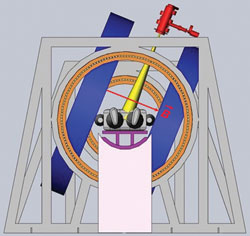
Figure 1 Transverse rotating biplanar geometry (electron beam is shown in yellow, and the MRI magnets are shown in blue). Reprinted with permission from Cross Cancer Institute.
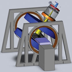
Figure 2 Longitudinal rotating biplanar geometry (electron beam is shown in yellow, and the MRI magnets are shown in blue). Reprinted with permission from Cross Cancer Institute.
The team explored two different configurations of this geometry; the transverse and longitudinal directions as shown in Figures 1 and 2. In the transverse geometry, the radiation beam could pass unimpeded through the open side of the MRI system (see Figure 1), but a hole was required for the beam to pass without interacting in the magnet poles in the longitudinal geometry (see Figure 2). Currently, both geometries are being pursued as each one has its clinical advantage.
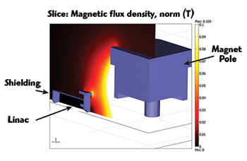
Figure 3 Quarter section cutaway of passive shielding for a perpendicular Linac-MR orientation (magnetic field lines perpendicular to electron trajectories).
Methods for Shielding
One of the earliest projects conducted by the team was to establish a means of shielding the linac from MRI’s strong static field, and MRI from the EM field generated by the linac. Because the linac’s tolerance to magnetic fields was unknown at that time (this was later investigated by this group), the aim was to shield the linac down to 0.5 gauss, the magnitude of the Earth’s magnetic field. To accomplish this, the team used a ferromagnetic shielding wall to concentrate the magnetic flux lines produced by MRI, preventing them from affecting the electron trajectories within the linac.5,6,7
The initial dimensions of the steel plate in the shielding wall were set to a thickness of 5 cm and dimensions of 2000 × 2000 cm. Using COMSOL Multiphysics, the team was able to verify the tolerances of the linac to the magnetic field and reduce the shield to a radius of 30 cm and a thickness of 6 cm (see Figure 3). The new shield was more than three times lighter than the original, much more practical from an engineering design point of view. This new shield also dramatically reduced MRI’s field inhomogeneities — by more than three times — which is important in producing a distortion-free MR image. And in addition to the optimized passive shielding arrangement that was devised, they also were able to develop an optimal active shielding solution that provided the same level of shielding for the linac but with an even further reduction in MRI field inhomogeneities.
As a complementary investigation to the simulations performed on the transverse geometry, analyses were performed to determine the linac’s tolerance for the longitudinal Linac-MR geometry. Both passive and active shielding were optimized, resulting in no increase in MRI image distortion and a fully functional radiation beam.
Optimizations that Fit the Standard Treatment Room
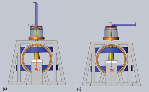
Figure 4 A long 10 MeV waveguide cannot be positioned vertically above the treatment table because it would be too large to house in a standard treatment room (a). Positioning the waveguide parallel to the treatment table introduces interactions that are difficult to shield from MRI (b). Reprinted with permission from Cross Cancer Institute.
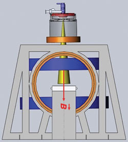
Figure 5 Orientation of the short 10 MeV waveguide in relation to the treatment table. Reprinted with permission from Cross Cancer Institute.
Initially, the prototype Linac-MR was designed with a 6 MeV waveguide; however, to treat the full range of cancer sites, a higher electron beam energy is needed to penetrate into tissues deep within the body. To produce higher x-ray energies of 10 MeV, a long (1.5 m) waveguide is needed to accelerate the particles (see Figure 4a). However, a longer waveguide would require buncher coils, solenoid coils and positioning coils along its length to prevent the deflection of the electron beam from the waveguide during treatment. In addition, due to the waveguide’s length, it would need to be positioned horizontally to the treatment table in order to fit into a standard-sized treatment room (See Figure 4b).8 This horizontal orientation of the waveguide would require the use of bend magnets to redirect the electron beam toward the patient, and the Lorentz forces introduced by the MR’s magnet would further deflect the electron beam out of the waveguide and require more shielding.2
Instead of using either of these orientations for the long 10 MeV waveguide, the team instead designed a shorter 10 MeV waveguide by optimizing it using simulation.2 They wanted the Linac-MR to generate a 10 MeV electron beam because it would allow the Linac-MR to treat the full range of cancers that necessitate the use of many different beam energies. Given the current resizing options, that would have meant using a waveguide that measured 1.5 m, too long for the system needs and requiring too much shielding. The team estimated that the shortest 10 MeV waveguide that could be designed using conventional S-Band techniques was 70 cm, but by performing additional simulations, they found that they could reduce the length of the waveguide to 30 cm (see Figure 5).
To date, no one has attempted to design such a linac. According to Dr. Stephen Steciw, Department of Medical Physics at the Cross Cancer Institute, the goal of designing a new S-Band linac is to use the same technologies currently available in the market, but to use them smarter. The team uses simulation software to push the current capabilities of existing technologies further by optimizing them to improve their performance.
To begin, the research team used a benchmark model of a single energy Varian 600C (6 MeV) S-Band waveguide produced by a former graduate student of the group, Dr. Joel St. Aubin, to analyze the effects of increasing the field strength to produce 10 MeV electrons. A significant concern when increasing the input power to the waveguide is electric breakdown. If the RF fields in the waveguide increase beyond the threshold determined by the waveguide geometry and operating frequency, electric arcing will occur within the waveguide, absorbing the RF energy and damaging the device. Using simulation, the team was able to determine that current S-Band technologies only use roughly 40 percent of the breakdown limit, allowing plenty of room for improvements to be made for a stronger waveguide.2
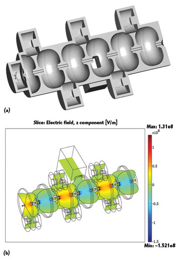
Figure 6 Cutaway view of the Linac system waveguide with RF cavities (a). Electromagnetic field distribution in a short 10 MeV waveguide (b).
COMSOL Multiphysics was used by a graduate student Devin Baillie, member of the team, to adjust the resonance frequency of the model and to calculate in 3D the RF fields that exist within the waveguide. This analysis was then used to determine the highest strength of the power source that could be used in the waveguide. The benchmark model, the Varian 6 MeV waveguide, uses a 2.5 MW magnetron power source. Using COMSOL to recalculate the RF fields within the waveguide, the team determined that a 7.5 MW klystron power source could be used instead, without the risk of causing electric breakdown.
The waveguide is composed of a number of RF cavities through which the electron beam is directed (see Figure 6). From previous work done by the group, they knew that the RF fields in the first half of the accelerating cavity, where the electrons enter the waveguide, are critical for electron capture within the waveguide and have a strong influence on the final energy spectrum. They determined that these RF fields could be reduced by optimizing the position of the first coupling cavity, thereby allowing for a stronger power source to be used. Results obtained from the model showed that, even with a threefold increase in input power needed to generate a 10 MeV waveguide (from 6 to 10 MeV), the peak surface fields of the waveguide are below the threshold limit, meaning that electric breakdown will not interfere with the operation of the accelerator (see Figure 7).2
With this shortened waveguide, the Linac-MR device is small enough that it can be fit into a standard-size radiation therapy treatment room. This factor was of the utmost importance to the success of the project, because it will enable the device to be easily installed in hospitals and treatment centers around the globe. Many radiation treatment rooms are housed in the basement, meaning that it would be next to impossible to expand the room to contain a larger device. Rebuilding the treatment rooms would be too costly to be implemented on a large scale. With a short 10 MeV waveguide, the Linac-MR is not only able to treat a wider variety of cancer types, but it can be easily set up in a typical treatment center as well.
Real-Time Tumor Tracking
Even with the ability to successfully shield a short 10 MeV waveguide, a system still needed to be developed to compensate for the motion that occurs during system delay as images are acquired and processed by the MRI and computer-controlled system, and as radiation beam modifiers move into place to deliver radiation therapy. This is especially important for tumors located in the lungs, liver or stomach, since it is impossible to prevent movement from occurring in tumors located in these areas.
This was accomplished using a system that could predict the future position of the tumor in space and time using a motion-prediction software and an algorithm developed by the team.9,10 The program works by taking several images per second during treatment, and then auto-contouring the images using an in-house software that determines the tumor’s shape and position. By tracking the past movements of the tumor, the system then predicts from this data where the tumor will be a few seconds in advance.
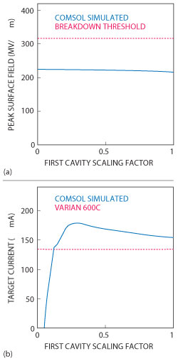
Figure 7 The maximum field magnitude (solid blue) compared with the breakdown threshold (dotted red), as the first cavity fields are scaled (a). The current in the electron beam striking the target simulated (10 MeV) waveguide (solid blue) compared with that of the unmodified (6 MeV) waveguide (dotted red) (b).
The accuracy of the motion-prediction software was determined using an MR tractable ‘phantom’ that was representative of a tumor. ‘Phantom’ tumor movements were tested in two different patterns: sine, representing periodic motion; and modified cosine, signifying lung tumor motion. Dosing film inserted inside the tumor phantom measured the tumor’s exposure to radiation and determined the accuracy of the software’s predicted future tumor position. Their algorithm, when used in both the sine and modified cosine trials, demonstrated a dose profile in the phantom that closely matched dose profiles in static targets. The ability to deliver a highly conformal dose to a target in motion was confirmed.
Conclusion
The Linac-MR is an enormous breakthrough for radiation treatment. In addition to improving the accuracy of radiation treatments for stationary tumors, it will also mean that certain types of tumors that are difficult to treat with radiation — such as those found in the liver, stomach and pancreas — can now include radiation as a treatment option. The prospects for mobile tumors are also drastically improved, since the Linac-MR can administer adequate doses to these moving tumors with sufficient accuracy to preserve surrounding healthy tissues. The Linac-MR prototype is currently undergoing its final tests, and the team is preparing the documentation required to seek governmental approval for the device to be used in clinical trials. The first real-time image-guide radiation treatment device, the Linac-MR, is expected to be in use as early as 2016.
References
- B.G. Fallone, B. Murray, S. Rathee, et al, “First MR Images Obtained During Megavoltage Photon Irradiation from a Prototype Integrated Linac-MR System,” Medical Physics, Vol. 36, No. 6, June 2009, pp. 2084-88.
- D. Baillie, J. St Aubin, B. Fallone and S. Steciw, “Feasibility of Producing a Short, High Energy S-Band Linear Accelerator using a Klystron Power Source,” Medical Physics. Vol. 40, No. 4, April 2013, pp. 41713-35.
- B. Burke, A. Ghila, B.G. Fallone and S. Rathee, “Radiation Induced Current in the RF Coils of Integrated Linac-MR Systems: The Effect of Buildup and Magnetic Field,” Medical Physics, Vol. 39, No. 8, August 2012, pp. 5004-14.
- J. St Aubin, D.M. Santos, S. Steciw, et al, “Effect of Longitudinal Magnetic Fields on a Simulated In-line 6 MV Linac,” Medical Physics, Vol. 37, No. 9, September 2010, pp. 4916-23.
- M. Reynolds, B.G. Fallone and S. Rathee, “Dose Response of Selected Ion Chambers in Applied Homogeneous Transverse and Longitudinal Magnetic Fields,” Medical Physics, Vol. 40, No. 4, April 2013, 042101/7.
- D.M. Santos, J. St. Aubin, B.G. Fallone and S. Steciw, “Magnetic Shielding Investigation for a 6 MV In-line Linac Within the Parallel Configuration of a Linac-MR System,” Medical Physics, Vol. 39, No. 2, February 2012, pp. 788-97.
- B. Burke, K. Wachowicz, B.G. Fallone and S. Rathee, “Effect of Radiation Induced Current on the Quality of MR Images in an Integrated Linac-MR System,” Medical Physics, Vol. 39, No. 10, October 2012, pp. 6139-47.
- D.M. Santos, J. St Aubin, B.G. Fallone and S. Steciw, “Magnetic Shielding Investigation for a 6 MV In-line Linac Within the Parallel Configuration of a Linac-MR System,” Medical Physics, Vol. 39, No. 2, February 2012, pp. 788-97.
- J. Yun, K. Wachowicz, M. Mackenzie, S. Rathee, D. Robinson and B.G. Fallone, “First Demonstration of Intrafractional Tumor-tracked Irradiation using 2D Phantom MR Images on a Prototype Linac-MR,” Medical Physics,Vol. 40, No. 5, May 2013, pp. 051718/12.
- J. Yun, E. Yip, B.G. Fallone, et al, “Evaluation of a Lung Tumor Autocontouring Algorithm for Intrafractional Tumor Tracking Using Low-field MRI: A Phantom Study,” Medical Physics, Vol. 39, No. 3, March 2012, 1481-94