
A GSM DIGITAL RADIO COMMUNICATIONS TEST SET
Marconi Instruments Inc.
Marconi Instruments Inc.Allendale, NJ
Without question, the Global System for Mobile communications (GSM) is the dominant digital cellular radio technology in use throughout the world. Originally designed for the European market, GSM has been adopted to meet the needs of cellular service providers in many countries due to its proven technology, worldwide roaming, good speech quality, extensive digital services, additional subscribers per megahertz and call privacy through encryption. While the majority of installed GSM systems are at 900 MHz, many new systems are emerging at 1.8 GHz (digital communication system (DCS)1800) and 1.9 GHz (personal communications service (PCS)/personal communications network (PCN)). DCS1800 is being installed worldwide and PCS 1.9 GHz is employed predominantly in the US, where it is competing directly with both North American Digital Cellular and code-division multiple access technologies. A recent report in the trade press estimated that PCS GSM would cover 98 percent of the US land mass by 2000 and capture more than two million subscribers.
The model 2967A GSM/DCS/PCS radio test set is an adaptation of the successful model 2966A GSM analog and digital radio test set that was launched in 1995. The model 2967A provides all of the comprehensive features and facilities of the model 2966A, but offers an extended frequency range to cover both DCS and PCS/PCN. In addition, the test set provides for the testing of all commercial and military high frequency single-sideband, AM, FM and phase-modulated radios, as well as all of the worldwide analog cellular radio standards.
This capability delivers extensive benefits to the user in terms of flexibility, cost, space and operator training. Flexibility is becoming more important due to the introduction of dual-mode, dual-band cellular radios where analog Advanced Mobile Phone Service is employed for fallback coverage in areas where PCS is not yet available.
GSM Base Station Emulation
It is essential for a GSM mobile telephone test set to emulate the base station infrastructure. Only in this manner can the telephone be tested to ensure that it operates correctly, obeys systems commands and reports requested information. The model 2967A provides all of the uplink and downlink signaling protocol requirements for the telephone to operate in a pseudoreal environment. This capability allows the test set to exercise and check air interface parameters such as broadcast control channel, traffic channel, registration, hand-off, power-level adjustment, timing advance, speech quality, bit error rate (BER) and received signal strength indicator.
Test Speed
Fast and accurate testing is an important factor in today's test environments. Minimizing testing costs and keeping the production or repair test cycle to a minimum are the keys to success in the highly competitive GSM telephone market. The speed of the model 2967A has been proven by benchmark evaluation to be up to four-times faster than some of its main competitors when conducting GSM mobile tests. This testing speed is achieved by the extensive use of digital signal processing, which allows accurate measurements to be returned quickly, thus facilitating a near real-time test environment. The 2967A test set also employs a multiprocessor architecture where many tasks are conducted in parallel, producing a corresponding improvement in test speed.
Signal Generation and Measurement Accuracy
Stimulus and measurement accuracy are also important factors in a world where quality counts and the need to get it right the first time is paramount. Here, the model 2967A excels with specifications that meet the demands of the production test and high level service environments. The comprehensive list of GSM tests have default pass/fail limits based on the European Telecommunication Standard Institute's GSM11.10 specification. Most of these tests also have pass/fail limits that may be set by the customer to enable tighter test specifications to be entered.
 The RF signal generator employs a patented digital fractional-N technology to produce an accurate 0.3 Gaussian minimum-shift keying (GMSK) modulated signal with fast switching speeds. Corresponding accurate signal analysis is provided for RF power, RF burst, frequency and phase measurements, as well as a high quality spectrum analyzer for spectral analysis, as shown in Figure 1 .
Automatic Testing
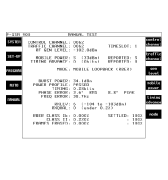
Production test demands easy and comprehensive remote programming facilities to allow for automatic test and results logging. The model 2967A has an internal Basic interpreter and many internal auto test routines with customer-selected pass/fail limits. Test results can be logged to a hard-copy printer or output to a PC database. In addition to four internal auto test sequences, the instrument contains a user-defined test program area for the operator to download a user test program for internal execution. Programs for this facility are written in the text-based Basic language, which may be generated on any Windowsª or DOS text editor. In this mode, the programmer has access to the many internal test routines through a single command, such as TX Power or TX Phase Error. Figure 2 shows the power profile of a signal burst, including specification limits. Figure 3 shows a digital duplex test display with bar graphs for easy alignment. Figure 4 shows a phase error display.
Figure 2 

Figure 3
Figure 4
Additionally, the unit may be controlled by a PC over the standard GPIB or RS232 interfaces by programs written in any of the popular high level languages such as visual Basic or C++. All of the internal test routines are available to the programmer by single command statements.
Fault Diagnosis
To allow for radio fault diagnosis and alignment test scenarios, the model 2967A provides a manual test-mode menu. This facility enables the entire range of test instruments that compose the test set to be used to solve the test problem. This manual mode allows the operator to generate stimuli signals with both RF and audio signal generators; inject these signals into the radio circuits; chase them through; and analyze the outputs on the RF and audio analyzers, power meters and spectrum analyzers.
Automatic Alignment
Usually, cellular radios will have an RS232 engineering control interface to command the various test modes of the telephone and to allow for easy upgrade of the telephone's software. The model 2967A includes a bidirectional RS232 interface with appropriate Basic programming capability that may be employed to control the mobile telephone, download parametric calibration data and upload parameter adjustment data. In this way, the alignment of the radio can be programmed and automated fully. Figure 5 shows an IQ modulator alignment display.
Measurement Features
 Fast and accurate measurements can be made of the telephone's peak power and burst profiles (power vs. time) at each of the 15 power levels (19 levels for phase II). These measurements may be taken either in the manual test mode, as shown in Figure 6 , or set up as part of an auto test sequence. A powerful power profile analyzer makes and displays measurements on the full burst with a zoom facility to either the data period or power ramp up/down display.
Frequency measurements are displayed as an offset from the absolute frequency of the current channel in both bar chart and digital readouts. The phase analyzer measures and displays both peak and RMS values. In addition, a graphical view of phase analysis is available with GSM11.10 limit lines to provide a visual display of the telephone's performance.
Receiver measurements such as sensitivity and BER tests on Class 1A, 1B and II bits together with the frame erasure rate are available in both manual and automatic test modes. BER and speech quality tests are facilitated by the loopback method where the mobile telephone transponds the pseudorandom bit sequence data to the test set for bit error measurements. For the speech test, the operator speaks into the telephone and the test back loops the signal after a preset delay. Mobile telephone-reported RX quality and RX level parameters are also decoded and displayed.
The spectrum analyzer may be used to inspect and measure IF and LO frequency conversion as well as to measure and display the GMSK spectral profile of the telephone's transmitter. The model 2967A will maintain the telephone in conversation while in the spectrum analyzer mode and will allow RF-to-IF conversion offsets to be entered. The analyzer also includes a full performance tracking generator with full offset capability to allow filter and mixer characterization.
The instrument interfaces include parallel and serial printer ports, GPIB and serial remote control ports, a Video Graphics Array color monitor port and a Personal Computer Memory Card International Association type II PC card memory facility. The PC card may be used to store instrument settings, system parameter settings and test results.
Ownership Cost
Capital cost, reliability and maintenance costs are major contributors to the overall operating budgets of modern test equipment. The 2967A test set is based on the mature and proven models 2965A and 2966A platforms designed with reliability and ease of maintenance in mind. The service and support facility at Fort Worth, TX is fully equipped to support, calibrate and repair the instruments in the US. All model 2966A instruments may be upgraded to model 2967A by the service center at a reasonable cost that will represent a considerable saving over the purchase of any competitive instrument.
Marconi Instruments Inc.
Allendale, NJ
(800) 233-2955