
Cable assemblies are some of the most widely used components in military and commercial electronic systems. They are used as connections between components within racks, subsystems, antenna feeds and various test platforms, among many others. Although a cable assembly looks like a very simple component, consisting of just coaxial cable and connectors, in many situations it can be the critical factor determining system performance, life and cost. Developing the most suitable and effective cable assembly for a particular application with a reasonable cost is a real challenge for every system or subsystem designer. Good communication between customer and vendor is necessary for the proper choice of cable, connector and assembly technique.
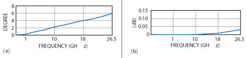
Figure 1 Phase stability (a) and amplitude stability (b) vs. flexure.
The designer/customer must first be able to transfer the requirement and specification for a cable assembly to the vendor/manufacturer of a cable assembly. Cable and connector selection are the next steps, possibly with assistance from the manufacturer, to ensure that all requirements are met within cost and delivery constraints. In some situations, existing cable and connectors are not suitable, and custom design may be necessary to meet the specifications. Assembly techniques must also be examined as they may dictate the use of alternative cable or connectors, due to manufacturing problems of availability, time, cost or quality. Finally, testing must be done at all stages to ensure that the assemblies meet electrical, environmental and reliability requirements. Test data will indicate whether the assembly procedures and techniques will produce a final product meeting all specifications and application requirements.
Test Cables
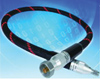
MIcable worked with one customer to develop a new DC to 26.5 GHz test cable assembly that uses a custom designed cable with 0.195" outer diameter, soft and flexible PVC jacket, solid PTFE dielectric and improved braid layer design. The strong and rugged connectors, special strain release design and improved assembly technique were used in the new cable assembly. This process of cable assembly design and manufacturing produced a new and successful assembly.
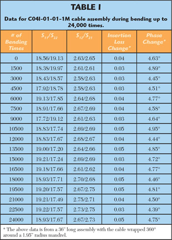
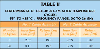
Figure 1 shows the 36" long cable has phase stability less than 4° and 6° with the cable wrapped 360° around a 1.95" radius mandrel at 18 and 26.5 GHz, respectively, with amplitude stability of 0.03 dB max. Table 1 and Figure 2 show that even after up to 20,000 bending cycles, the VSWR, insertion loss and phase/amplitude stability exhibits almost no change. Table 2 shows good electrical performance with the same tests after 25 temperature cycles from -55° to +85°C. Customers have been pleased with this DC to 26.5 GHz test cable assembly after they evaluate and compare it to others.
Phased Array Cable
Phased array radar has become an important product around the world but has inherent problems for cable assembly manufacturers. Large numbers of assemblies are needed with close matching, making the specifications difficult to consistently manufacture. Airborne phased array system manufacturers state that their biggest problem is phase mismatching during rapid altitude change. Calibration will not correct the situation and cable assembly manufacturers have had many unsuccessful attempts to solve the problem. In addition, phase tracking over temperature is an equally important specification that the system engineers really should require. Many system engineers incorrectly emphasize the cable’s phase stability over temperature instead of phase tracking. A tight phase tracking specification is the correct goal to achieve good phase matching over wide altitude and temperature variation. Making good phase tracking cable assemblies is a very big challenge, requiring strict consistency in materials and manufacturing techniques.
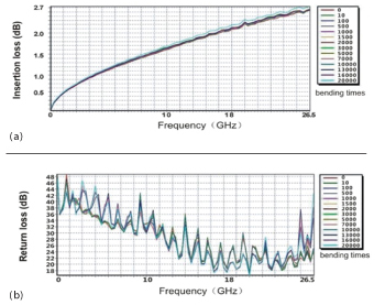
Figure 2 Insertion loss change (a) and return loss change (b) over 20,000 flex cycles (C041 cable assembly, 1 m).
MIcable has also designed cable assemblies for phased array radar application with a wide temperature range. MIcable has developed a set of comprehensive methods, including cable evaluation, connector design, manufacturing and assembling techniques, and inspection and testing procedures. The cable was chosen from a well known supplier, QPL approved, where previous experience had shown that they had high standards and good cooperation. Connectors were designed and tested in the company’s facility and elsewhere for approval. To control quality and consistency, inspection after every process was emphasized and workers trained to IPC J-STD-001 and IPC/WHMA-A-620 standards. Rapid phase correcting techniques were developed; and computerized semi-rigid bending machines, fast and precise stripping equipment, and PNA vector network analyzers were utilized. Quality systems according to MIL-I-45208 and MIL-STD-2219 were used, along with ISO 9001 and China GJB-9001B-2009 standards.
Figures 3 and 4 show the test data for three phased array cable assemblies of each type. From the data, the temperature tracking performance of the cable assemblies was controlled within a very small range. The different cable assemblies have good consistency, proving the capability to offer good temperature tracking performance. As shown, B01-40-40-1M phase stability versus flexure is ±8° at 40 GHz, bend radius of 51 mm and phase stability versus temperature of 500 ppm from -40° to about +85°C. A041-01-01-1M phase stability versus flexure is ±5.4° at 18 GHz, bend radius of 76 mm and phase stability versus temperature of 250 ppm from +22° to about +100°C with power handling of 500 W at 10 GHz. From this performance, the company delivered 9 km of phased array flexible cable assemblies and a 1400 piece order for bent semi-rigid cable assemblies, with three bends, a minimum bending radius of 6 mm and matching and tracking within 1° over -40° to +70°C over all cable assemblies. The products were delivered within two weeks. The semi-rigid cable is shown in Figure 5.
As the commercial and military markets come up with more strict challenges for higher performance and longer life for cable assemblies, a good combination of component design and assembly techniques are more important than ever before. The cable assembly designer/engineer must understand the customer’s application and know how to transfer the application demand to the requirement of the cable assembly. The cable assembly manufacturer must then be able to source the proper components, assemble them with advanced techniques and equipment, and be alert for changes to meet the specifications and requirements of the project. Good communication between all parties is absolutely necessary – good teamwork is a must.
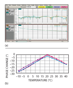
Figure 3 B01-40-40-1M insertion loss (2.97 dB max) and VSWR (1.23:1) data from DC to 40 GHz (a) and phase tracking vs. temperature at 40 GHz (b).
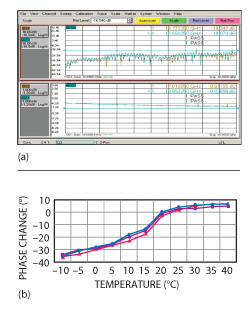
Figure 4 A041-01-01-1M insertion loss (0.91 dB max) and VSWR (1.25:1) data from DC to 18 GHz (a) and phase tracking vs. temperature at 18 GHz (b).
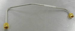
Figure 5 Bent phase matching and tracking semi-rigid cable assemblies with phase match and phase tracking ≤1° at 2.3 GHz.
MIcable is a joint venture by US SSI Cable, a leading cable assembly company and Mitron, a leading distributor and agent for microwave products in China.
MIcable Inc.,
Fuzhou, Fujian, China,
sales@micable.cn
www.micable.cn