
Cable assemblies are some of the most widely used components in military and commercial electronic systems. They are used as connections between components within racks, subsystems, antenna feeds and various test platforms, among many others. Although a cable assembly looks like a very simple component, consisting of just coaxial cable and connectors, in many situations it can be the critical factor determining system performance, reliability and cost. Developing the most suitable and effective cable assembly for a particular application with a reasonable cost can be a challenge to the system or subsystem designer. Good communication between customer and vendor is necessary for the proper choice of cable, connector and assembly technique.
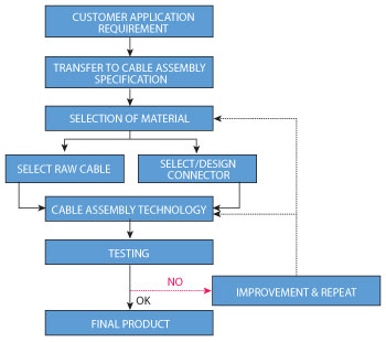
Figure 1 Flowchart of cable assembly development.
The designer/customer must first be able to transfer the requirement and specification for a cable assembly to the vendor/manufacturer. Cable and connector selections are the next steps, possibly with assistance from the manufacturer, to ensure that all requirements are met within cost and delivery constraints. In some situations, existing cable and connectors are not suitable, and custom design may be necessary tomeet the specifications. Assembly techniques must also be examined as they may dictate the use of alternative cable or connectors, due to manufacturing issues such as availability, time, cost or quality. Finally, testing must be done at all stages to ensure that the assemblies meet electrical, environmental and reliability requirements. Figure 1 shows a typical development cycle for cable assemblies.
Customers often ask why some vendors make better cable assemblies than others, even though they use identical cable and connectors. Experience and knowledge of proper assembly techniques can be the answer. Modern electronic systems are expensive and complex and need to be dependable so cables should not be a source of any problems with proper selection of components and manufacturers.
Below are two successful examples showing how cable assemblies were developed for a commercial and military application.
DC to 26.5 GHz Test Cable Assemblies
Test cable assemblies are among the most difficult to make of all cable assembly demands. In many production situations, test cable assemblies are used multiple times daily and their performance and reliability will directly affect the customers’ product performance and cost.
Performance requirements that customers expect for test cable assemblies:
- Very flexible with small bending radius for convenient use
- Very small phase change versus flexure
- Low amplitude/insertion loss change with movement and bending
- Consistent good performance over time and frequent use
- Low cost
A good test cable assembly, therefore, needs to be ultra flexible and amplitude/phase stable with a long life and low cost.
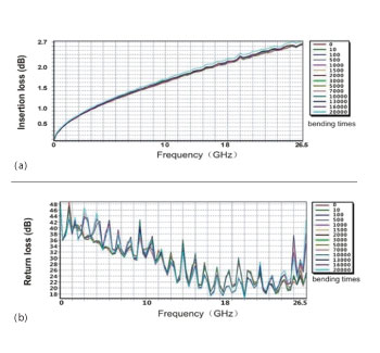
Figure 2 Insertion loss change (a) and return loss (b) measured over 20,000 flex cycles (C041 cable, 1 m).
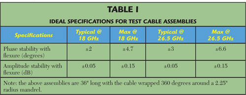
The first step in developing a new product is making the decision about product requirements and specifications. For test cable assemblies, the most important specification is phase and amplitude stability with flexure. Table 1 lists the market specifications found in various published materials for test cables.
Considering that the new product should be competitive in the market, the cable assembly should have the following specifications:
- Equal or better than the best electric performance in the market, better than the specifications listed in Table 1.
- The cable should have a small bending radius and be very flexible. For this example, it was decided to select 0.195" as the outer diameter of the cable and 1.95" radius mandrel instead of the Table 1 2.25" radius as the test condition for phase and amplitude stability.
- The assembly should have better reliability and longer life compared to presenproducts in the market.
- The assembly should have a competitive cost compared to present products in the market.
In the process of developing the example test cable assembly, the following steps were taken:
- Work with the cable manufacturer for special custom designed cables according to the requirements.
- Improve connector design to a more rugged and easily assembled configuration, so the cable is well protected.
- Use a stronger connector strain release design so the life of the cable assembly can be extended and the assembly can have a shorter bend radius.
- Improve assembly techniques to counteract the differential expansion coefficient of the dielectric and center conductor, for better mechanical reliability and electric performance.
- Develop a complete test method to check the performance as well as the long term reliability.
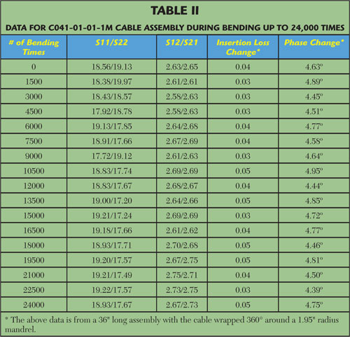
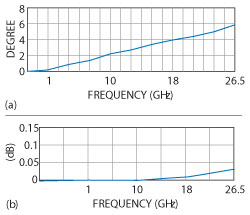
Figure 3 Phase stability (a) and amplitude stability (b) versus flexure.
The example DC to 26.5 GHz test cable assembly uses a custom designed cable with 0.195" outer diameter, soft and flexible PVC jacket, solid PTFE dielectric and improved braid layer design. The rugged connectors, special strain release design and improved assembly technique were used in the new cable assembly. This process of cable assembly design and manufacturing produced a new cable that meets all of the requirements. Listed in Table 2 is the test data of the new cable assembly and Figure 2 is a plot of the change in insertion loss and return loss over 20,000 bend cycles showing little change over the entire frequency range to 26.5 GHz.
Phase and amplitude stability plotted in Figure 3 show that a 36" long cable has phase stability less than 4° and 6° with the cable wrapped around a 1.95" radius mandrel at 18 and 26.5 GHz, respectively, with amplitude stability of 0.03 dB max. The data shows that after up to 20,000 bending cycles, the return and insertion loss plus the phase and amplitude stability exhibit little change. The cable also shows good electrical performance with the same tests after 25 temperature cycles between -55° and +85°C (see Table 3). The bending machine used for exercising the cables is shown in Figure 4.
Phased Array Radar Application
Phased array radar has become an important product around the world but has inherent problems for cable assembly manufacturers. Large numbers of assemblies are needed with close phase matching, making the specifications difficult to consistently reproduce.
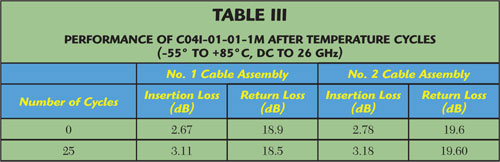

Figure 4 Bending machine for performing cable flexure.
When system engineers select cable assemblies for phased array systems, the following requirements are needed:
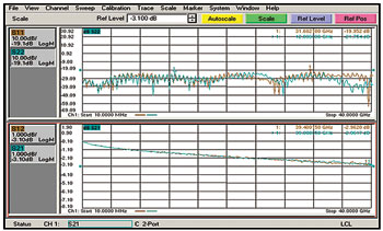
Figure 5 B01-40-40-1M test data from DC to 40 GHz.
- The cable needs to have low loss, high power capability and close tolerances.
- The cable must meet excellent phase matching specifications, with little phase change while bending, during vibration, and with temperature fluctuation.
- Phase matching requirements are needed for large quantities.
Airborne phased array system manufacturers state that their biggest problem is phase mismatching during rapid altitude change. Calibration will not correct this issue and cable assembly manufacturers have had a hard time correcting this problem. In addition, phase tracking over temperature is an equally important specification that the system engineers should require for the product. Many system engineers incorrectly emphasize the cable’s phase stability over temperature instead of phase tracking. A tight phase tracking specification is the correct goal to achieve good phase matching over wide altitude and temperature variations. Making good phase tracking cable assemblies is a big challenge, requiring strict consistency in materials and manufacturing techniques.
Cable assembly manufacturers should have the following capabilities to properly address the problems in phased array systems:
- Helping the customer select the cable that is most suitable to the application.
- Producing high performnce phase matching and tracking cable assemblies, with the ability to produce large numbers of consistent assemblies.
- Strictly controlling the consistency of the materials and manufacturing techniques so that the specifications of phase and amplitude can be met during variations in environmental conditions.
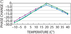
Figure 6 B01-40-40-1M phase tracking versus temperature.
A set of comprehensive methods was developed, including cable evaluation, connector design, manufacturing and assembling techniques, and inspection and testing procedures, in order to produce products that met this type of application’s requirements. Cable was chosen from a well known supplier, QPL approved, that previous experience had shown high standards. Connectors were designed and tested thoroughly. To control quality and consistency, inspection after every process was emphasized and workers trained to IPC J-STD-001 and IPC/WHMA-A-620 standards. Rapid phase correcting techniques were developed and computerized semi-rigid bending machines, fast and precise stripping equipment and PNA vector network analyzers were utilized. Quality management systems according to MIL-I-45208 and MIL-STD-2219 were used, along with ISO 9001 and China GJB-9001B-2009 standards.
Figure 5 shows the test data for three phased array cable assemblies (B01-40-40-1M) from DC to 40 GHz with insertion loss of 2.97 dB max., VSWR of 1.23:1, phase stability vs. flexure of ±8° at 40 GHz (bend radius: 51 mm), and phase stability vs. temperature of 500 ppm max. @ -40° to ~+85°C. Figure 6 shows the measured phase tracking plots for these cables’ phase tracking with a max. phase change inconsistency of 1.6° for every 5°C from -10° to 40°C for three different cable assemblies.
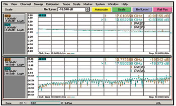
Figure 7 A04I-01-01-1M test data from DC to 18 GHz.
Figure 7 shows the test data for 3 DC to 18 GHz cable assemblies (A04I-01-01-1M) with insertion loss of 0.91 dB max., VSWR of 1.25:1, phase stability vs. flexure: ±5.4° at 18 GHz (bend radius of 76 mm), phase stability vs. temperature 250 ppm max. @ +22° ~+100°C, and power handling of 600 W at 10 GHz. Figure 8 shows the phase tracking data for (A04I-07-07-1.5M) at 18 GHz with a max. phase change of 3.8° for every 5°C from -10° to 40° for three different cable assemblies.
Finally, bent phase matching and tracking semi-rigid cable assemblies were manufactured with a minimum bending radius of 6 mm with phase match ≤1° at 2.3 GHz, phase tracking ≤1° at 2.3 GHz. Manufacturing was able to deliver 1400 pieces in two weeks (see Figure 9). As the data shows, the temperature tracking performance of the cable assemblies was tightly controlled. The cable assemblies have good consistency, proving the capability to offer good temperature tracking performance over volume production.
Conclusion
As the commercial and military markets demand higher performance and more reliable cable assemblies, a good combination of cable design and assembly techniques are more important than ever before. The cable assembly designer/engineer must understand the customer’s application and know how to transfer the application demand to the requirement of the cable assembly. The cable assembly manufacturer must then be able to source the proper components, assemble them with advanced techniques and equipment and be alert for changes to meet the specifications and requirements of the project. Good communication between all is absolutely necessary – good teamwork is a must.
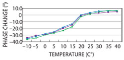
Figure 8 A04I-07-07-1.5M phase tracking versus temperature at 18 GHz.
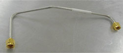
Figure 9 Semi-rigid phase matching and tracking cable assembly.