
Consumer appetite clearly demonstrates the demand for feature-rich, portable, communication devices that provide always-on connectivity, content and communication, or what we call c3. This c3 demand fuels the disruptive smartphone revolution and dramatically alters the cellular handset space in many ways. One fundamental outcome of this revolution has been the creation of an almost perfect power consumption vicious cycle. The cycle begins with the quest for c3 propelling increased data bandwidth, which enables greater baseband processing power and display sophistication. The cycle repeats as increases in processing power and display sophistication have driven improved mobile applications to take advantage of c3. Battery power consumption demands mushroom at each step in the cycle and in each smartphone generation.
Power Consumption Trends
Smartphone power consumption trend analysis yields insightful drivers and results. Clearly, each successive smartphone generation significantly increases power consumption. In the past, inclusion of the latest radio link technologies (2G/2.5G/3G/4G) predominately drove handset power consumption. Radio link power consumption increases were modest when compared to relative bandwidth gains. Handset bandwidth gains, however, resulted in explosive overall power consumption, driven by high resolution displays and sophisticated applications processors. For example, during the last three years, RF power consumption increased by 11 percent, while processor and display power consumption each increased more than 200 percent.
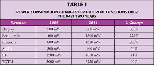
The increasing overall power consumption curve encourages innovative approaches to power management. Power management starts with the battery. Most smartphones use a Lithium polymer battery with an energy density of approximately 0.13 mAh/mm3 at a nominal 3.7 V. Growing smartphone power demands have traditionally been met by increasing battery capacity through increasing physical battery size and, as a result, battery capacity has increased approximately 10 percent per year for the last several years. The rate in battery capacity increase has been unable to keep pace with the power demands resulting from the vicious power cycle driven by c3. Table 1 shows the increased power demand for the different functions in the past two years.
Until recently, the RF cellular power amplifier (PA) significantly drove the handset power consumption curve. As such, the RF PA has been a significant target for efficiency gains. The latest 3G-generation of cellular PAs average more than 45 percent efficiency. A reasonable rule of thumb in current smartphone generations is that 1 percent point of PA efficiency improvement translates to approximately 35 mAh of battery capacity. Looked at another way, a 1 percent point improvement in PA efficiency translates to approximately 50 mm2 of recoverable footprint area in today’s ubiquitous smartphone form factor. As the smartphone form factor has generally stabilized, due to ergonomic form-factor limitations, the efficiency driven footprint reductions translate into additional features, increased battery size, or both.
RF Power Management
From an outside perspective, the cellular PA appears a relatively simple device. It takes energy from the battery and directs it to the antenna. The PA has traditionally been directly connected to the battery without significant power management. As the battery voltage rose and fell (based on its charged capacity), the voltage available to the PA essentially followed. The 3.9 to 2.5 V range of the standard Lithium polymer battery (over full to empty capacity) results in design-related efficiency tradeoffs of direct battery connected PAs. The inclusion of PA power management DC-DC conversion allows PA efficiency design gains. The simplest converter uses a buck topology. The buck converter bucks high battery voltage to a lower, regulated level. Not surprisingly, this regulated bucked voltage level (typically targeted at 3.4 V) matches the average voltage (nominally 3.7 V) found over the significant portion of a Lithium polymer battery capacity profile. The buck regulator compensates for the high voltage level found on a fully charged battery. Once the battery voltage falls below the regulated level, the buck converter “drops out” and the PA is once again essentially directly connected to the battery. A buck converter allows the PA designer to maximize the efficiency of the PA by minimizing the need to deal with the higher end of a relatively wide battery voltage dynamic range. PA linearity performance suffers, however, as the voltage level drops on the battery as capacity is exhausted.
PA designers prefer a constant and relatively high supply voltage. The constant and high voltage leaves the PA designer with a reduced set of design tradeoffs between gain, linearity, efficiency, stability and ruggedness. This is where the newer boost/buck power management topology comes into play. The boost/buck converter operates in two modes. When the battery is nearly full (voltage level near maximum), the regulator operates in the buck mode providing a lower stabilized voltage. As the battery capacity diminishes, the battery voltage declines through an inflection point, where the regulator switches from buck mode to boost buck mode. As the name implies, the boost mode boosts the available PA supply voltage to a regulated voltage level above the currently available battery voltage. A typical boost buck PA DC-DC converter is essentially a high efficiency dedicated switching power supply. In order to minimize the size of the inductors needed (saving both space and cost), highly efficient boost buck converters operate at very high switching rates. The boost buck converter provides a tightly controlled voltage source allowing the PA designer to optimize the PA design without highly dynamic battery voltage constraints.
Cellular Power Amplifier Architecture
The cellular PA architectural topology constantly evolves to keep pace with the vicious power cycle. Traditional, high-performance, smartphone PA designs used quadrature balanced architectures. The balanced architecture was implemented for multiple generations, primarily because it balanced the need for efficiency against the need for voltage standing wave ratio (VSWR) tolerance. Remember that most PAs are typically directly connected to the handset antenna through a switch/filter network, which means that PA efficiency is directly tied to the quality of the impedance match between the output of the PA and the input of the antenna (or switch/filter network front end module). A better impedance match yields better efficiency. Handset antennas and their environment, however, routinely and dynamically change impedance. A tremendous number of both static and dynamic variables, including antenna material, location, and proximity/orientation to the human body, influence this pronounced impedance change. Impedance mismatch is measured by VSWR. Traditionally, PAs have been designed to meet high VSWR requirements to deal with the unpredictable environment.
Unfortunately, the quadrature, balanced architecture is not the most efficient PA architecture. If the VSWR requirement was relaxed, PA designers would take advantage of the higher efficiency single-ended (SE) architecture. The SE architecture gains efficiency at the expense of limited VSWR tolerance. Fortunately, the ability to control the antenna mismatch through traditional passive design approaches has nearly reached its limit. Several factors drive the inability to control antenna mismatch, but new active antenna control solutions generally result. Active antenna control solutions (ACS) essentially eliminate impedance mismatch. More importantly, the SE topology unlocks efficiency gains as ACS significantly reduces VSWR. ACS obviously comes at a cost, but other unrelated factors in handset design may encourage ACS. Of course, SE will work with passive impedance matching solutions as long as the VSWR range can be guaranteed through design. SE PA solutions are another weapon for combating the vicious power cycle.
Envelope Tracking for Cellular Power Amplifier
Both boost/buck power management and SE architecture improvements are relatively transparent to the system designer and independent in nature. Both approaches provide reasonable efficiency improvements to the handset system designer, with a defined cost/benefit tradeoff. Of course, the vicious power cycle continues driving new, innovative, approaches to efficiency improvements. Envelope tracking (ET) is the latest emerging technique and a dramatic shift to the handset RF PA design approach. The ET solution relies heavily on the tightly interwoven coordination of power management and PA architecture. In traditional PA architectures, using average power tracking (APT), PA energy consumption remains relatively stable regardless of the content of the transmitted data. To transmit, the PA is turned on and fed a steady amount of energy that is either dissipated in the PA (generating wasteful heat), passed to the antenna, or a combination of both. ET turns this convention on its head. In an ET system, the amount of energy provided to the PA dynamically changes as the content to be transmitted changes. Instead of dissipating significant amounts of energy in the PA, the PA is only provided with the energy that it will pass directly to the antenna.
An oversimplified analogy is as follows: In a traditional architecture, the amount of energy needed to transmit four bits of data is constant, regardless of the value of each individual bit. The ratio of energy dissipated in the PA versus provided to the antenna does vary as the makeup of the four bits varies, but the overall average power consumption is constant. In an ET system, the amount of energy needed to transmit four bits of data varies as the value of each individual bit varies. Most of the energy in an ET system is provided directly to the antenna with very little energy dissipation occurring in the PA. Now imagine a stream of bits creating a constant envelope of data. In a traditional system, the PA is provided constant average power for the duration of the envelope. In an ET system, the PA is provided with power that closely tracks the envelope. The amount of envelope tracking power is dynamic and depends upon the makeup of the data. Less power for the same result equates to increased system efficiency.
While the concept is straightforward and well understood, the level of coordination required between power management and PA in an ET architecture is significant and unprecedented in handset design. This coordination requires hardware-level design optimization and interaction to insure each component of the system contributes appropriately within an ET-optimized system. The ET-related system efficiency improvements are another arrow in the quiver to battle the vicious power cycle.
Conclusion
Each of the three described design techniques approaches system efficiency and power management from different angles. Cellular PA power conversion, cellular PA design architecture and envelope tracking focus on reducing the cellular PA impact on smartphone power consumption. Of course, each degree of power management sophistication comes with increasing costs in both footprint and component BOM costs. These are cost tradeoffs available to the smartphone system designers to choose from, in their never-ending quest to balance the vicious power cycle.