
Long Term Evolution (LTE) is a state-of-the-art standard for wireless communication, currently in technical implementation.1-5 The standard has been defined by the 3GPP organization and is publicly available – every engineer, researcher or student can download the official specification from www.3gpp.org. The 3GPP organization manages an international project called Evolved Packet System (EPS), which is widely known as “the 4th generation of mobile telecommunication systems (4G).” The Evolved Packet System includes the entire architecture of the 4G mobile systems, both packet network and radio interface. LTE is a part of the EPS project, which refers to a 4G air interface standard. Currently many companies in the world, as well as many universities, conduct research and development on this technology.
The authors of this article are involved in research on signal processing for LTE systems and they found that there is a lack of free software able to generate LTE signals. Although open source advanced LTE system simulators exist, no easy-to-use public domain signal generators exist to be used in signal processing research and development.
This article presents a MATLAB toolbox to fill this gap. Functions able to generate the downlink LTE signals are the main part of the toolbox. Together with the functions, a module named “LTE Professor” is presented. LTE Professor is a Graphical User Interface (GUI), which is able to generate LTE signals, analyze these signals and visualize LTE time/frequency resources utilization. The whole source code is GPL licensed and is publicly available at the authors’ website.6
The present article is divided into two main parts. The first part is an introduction to the LTE downlink Physical Layer. Here the basics of the LTE downlink time/frequency resources and signal generation are discussed. The second part of the article presents usage and architecture of the software, together with some examples of generated LTE signals.
LTE Downlink Introduction
The 4th generation of mobile telecommunication systems has, at least in theory, very good performance parameters in comparison to the previous generations.3 Unfortunately, this gain came at a price of significant complication of the whole system. The LTE protocol stack is divided into several layers. Additionally, there is a distinction between the downlink and uplink protocol stacks, since there are significant asymmetries between the different directions of data transmission. Description of the entire LTE system would exceed the limitations of a single article. Therefore, this work is focused on a MATLAB toolbox which emulates the LTE downlink transmitter. This transmitter translates code words, which are the input to the transmitter, into the LTE radio signal. The software is dedicated to engineers and scientists who are involved in research on modern communication signals and systems. In particular, this toolbox is useful in simulation of the LTE base station (BTS) transmission circuits, antenna systems and User Equipment (UE) receiver front ends. It can also be practical in the investigation of the LTE and Orthogonal Frequency Division Modulation (OFDM) channel models. In addition, this software can cooperate with models of higher LTE downlink layers.
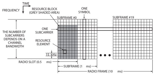
Figure 1 Time/frequency resources organization in the LTE.
During the downlink, data is passed from a BTS to a number of UEs, which are currently within range of the BTS. To provide downlink data transmission service for multiple users, LTE systems use OFDMA. The baseband signal is created using OFDM. In OFDMA, resources are represented in a time/frequency plane (see Figure 1) – one Resource Element (RE) is an atomic unit in the plane. The LTE standard fully supports multi antenna technology, so there may be up to eight time/frequency planes.
The accessible bandwidth is divided into a number of subcarriers.7 In the LTE standard, the separation between subcarriers is 15 kHz during regular transmission. Subcarriers are gathered in Resource Blocks (RB), where one RB consists of 12 subcarriers. The number of subcarriers depends on the size of the baseband. However, there is always an integer number of resource blocks in the baseband. There are six possible bandwidths in the LTE standard: 1.4, 3, 5, 10, 15 and 20 MHz.
The time organization is a bit more complicated.1,3,7 One symbol is an atomic unit of the time/frequency plane. The base length of a symbol (ts) is equal to a multiplicative inverse of the subcarriers’ separation, so ts = (15 kHz)-1 = 66.7 µs. The Inverse Fast Fourier Transform (IFFT) operation is used to generate a downlink signal. To ensure reliable transmission, a copy of the last part of a symbol is copied to the beginning of every symbol, this copy is called ‘Cyclic Prefix’ (CP). Cyclic Prefix has a length tCP and this length may differ, depending on the current CP settings. There are two basic CP settings: normal CP and extended CP.
The symbols are grouped in Radio Slots (RS). The duration of a single RS is always 500 µs. The number of symbols in one RS depends on the cyclic prefix type currently in use. There are six symbols in one RS in the case of the extended cyclic prefix. In the case of the normal cyclic prefix, there are seven symbols in one RS. Additionally, in the latter case, every first symbol in an RS has a longer cyclic prefix.
A longer LTE time unit is a Subframe (SF). The subframe has a time length of 1 ms and consists of two Radio Slots. A group of consecutive ten Subframes constructs a Radio Frame (RF). The RF is the longest time unit in the LTE standard. The duration of one RF is 10 ms (see Figure 1). In the LTE downlink, bandwidth resources are granted to a specific UE as a group of resource blocks. The resource assignment is renewed in every SF and cannot be changed until the end of an SF.
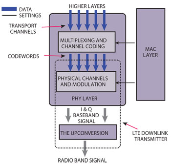
Figure 2 The LTE downlink transmitter in the LTE stack.
The MATLAB Models of the LTE Transmitter
LTE Downlink Transmitter
Figure 2 shows the position of the LTE downlink transmitter in the LTE protocol stack. There are two main parts of the LTE Physical Layer responsible for processing data from the higher layers. The upper part is responsible for multiplexing and channel coding.8 The bottom part is responsible for physical channels modulation and mapping to the resource elements.7 The MAC layer controls the entire physical layer.1,3,7,8 The presented MATLAB model emulates the bottom part of the Physical Layer.
The resource planes, in which signals and channels are mapped, are given to the OFDM modulator. The modulator generates the baseband signal. The baseband signal is then up-converted to the LTE radio signal. The presented software emulates both the baseband signal generator and the radio frequency generator. The baseband in-phase and quadrature signals (I and Q signals), as well as the radio frequency signal are the output from the presented model. Additionally, users have access to the resource planes and modulation symbols mapped to all physical signals and channels.
Downlink data comes to the transmitter in the form of code words. Code words are mapped to physical channels. Different physical channels can be in use depending on the current type of transmission. In the LTE standard, different types of transmission are used on different Antenna Ports (AP). The implemented MATLAB model supports the most common type, the transmission with Cell Specific Reference (CSR) signals.7 The multi antenna transmission is supported. In the current software version, the first and the second transmission modes are implemented.
The LTE Transmitter Model and Supplementary Software
The presented MATLAB model is available in the form of a toolbox. The detailed description of the toolbox can be found in ref. 6. The ‘LTE scenario’ structure must be passed as an argument to the main generator function. This structure is necessary to run the generator. It groups user settings and settings coming from the MAC layer. The toolbox contains examples of LTE scenario files to be used by users as a base for their own LTE scenario.
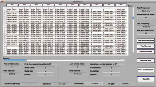
Figure 3 Screen shot of the LTE Professor.
The second data structure passed to the generator is a structure with code words data. In general, this structure is not required since in the case of no input data, the LTE generator sends random bits. Additionally, it is possible to include code words only for a few physical channels – the missing data will be randomly generated.
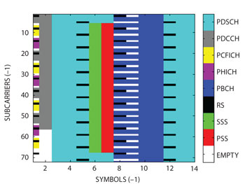
Figure 4 LTE signals and physical channels map made by the software (1.4 bandwidth).
The generator returns one structure. Obviously, this structure contains the baseband and radio band signals. Beside these signals, there are resource matrices that indicate signals/channels mapping and modulation mapping, matrices with symbols mapped to particular channels and structures with LTE Physical Layer specific parameters. The detailed description of this structure can be found in ref. 6.
The next essential part of the presented toolbox is the ‘LTE Professor’ module. This module consists of two main parts. The first part is dedicated to be a graphical interface for the developed MATLAB LTE model functions. With this part, users are able to set all parameters of the LTE scenario used by the LTE transmitter function. It is possible to get information about time and frequency parameters of the signal, which corresponds to the adjusted scenario settings. Finally the user is able to generate the LTE downlink signal and store it in the chosen file.
The second part of the LTE Professor is able to analyze and visualize generated signals. Users can observe the detailed view of the signals and channels mapping. This view gives information about modulation schemes and values mapped to all Resource Elements used in the analyzed LTE signal (see Figure 3). It is possible to generate the indicative ‘helicopter view’ of the entire resources plane (see Figure 4). Moreover, the entire LTE signal, as well as every particular LTE symbol in the generated transmission, can be viewed and analyzed in the frequency and time domains (see Figures 5 and 6). The extensive description of the LTE Professor is available.6
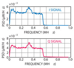
Figure 5 Power spectral density of the baseband signals (1.4 MHz bandwidth).
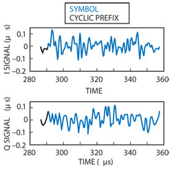
Figure 6 Baseband signals in the time domain (1.4 MHz bandwidth).
The validation of the software was performed in a few different ways. The LTE Professor module, which is also a part of the presented toolbox, was originally dedicated to validate the generator. The generated signals were analyzed with the LTE Professor. Mapping of LTE signals into time/frequency resources were compared with the maps that can be found in the literature. Additionally, the peak-to-average power ratio of the generated LTE bandwidth signals was measured to ensure that the generated signals are correct.
The Software Internals
Figure 7 shows the architecture of the implemented MATLAB models. The main ‘LTE_DL1a’ script controls the whole process. The LTE Resource Parameters Calculation (RPC) unit is run as the first sub module. This unit generates three structures: ‘sP,’ ‘sF’ and ‘sT,’ which contain LTE system parameters, LTE bandwidth parameters and LTE time parameters, respectively. These three structures are used in all later steps of the LTE signal generation. After running the RPC unit, three identical matrices are allocated in the Resources Allocation (RA) unit. These matrices reflect the time/frequency resources. The number of rows in the matrices is equal to the number of subcarriers and the number of columns is equal to the number of symbols in the entire LTE transmission. The reference and synchronization signals are added in the Signals Mapping (SM) unit. The channels are mapped to the time/frequency resources in the Channel Mapping (CM) unit.
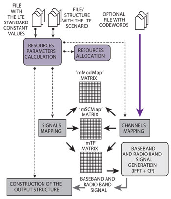
Figure 7 The LTE transmitter model architecture.
When all signals and channels are mapped to the LTE resources, the IFFT module generates the pure OFDM signal (without CPs). Adding cyclic prefixes to the pure OFDM signal generates the final baseband signal. Afterward, the signal is up-converted to the radio frequency.
Example of Signals Generated by the Software
Figure 5 shows the power spectrum density of the example baseband signal generated by the software. The signal on this figure is a 1.4 MHz LTE baseband signal. It appears that the power is not uniformly distributed, which is due to the nonuniform channels and signals mapping. In the LTE standard, not all resource elements are in use during transmission. Rules of the channel and signal mapping can vary due to the current bandwidth settings.
In Figure 6, the above LTE baseband signals are shown in the time domain. The time length of the shown signals is equal to the time length of one symbol with a cyclic prefix. The cyclic prefix, marked in black, is exactly the same as the last part of the symbol – it is correct according to the LTE standard. The presented plots are generated automatically using the LTE Professor software. A screenshot of this software, with a view on the resource elements with mapped signals and channels, is presented in Figure 3. Figure 4 shows the LTE signal in the time/frequency domain. The resource elements, in which the LTE signals and channels are mapped, are depicted. This map is generated by the ‘helicopter view’ option in the LTE Professor. The map presents the first Subframe in the Radio Frame.
The signal presented is just an example of the LTE signal that can be generated by the software. Hence, due to the GUI interface and predefined scenarios delivered with the software, it is easy to generate signals that correspond to the demands of the user. With relevance to reproducible research, the authors prepared MATLAB scripts that can be used to generate the presented signals. The scripts are available on the project website.6
Conclusion
The MATLAB toolbox, which is able to generate LTE downlink signals, has been presented. This program is published under the GPL open source license. The authors have prepared a website where the code is available for users. The website also contains a blog about the MATLAB LTE signal generator and a message board for information and comments exchange. The signals generated by the software are also included.
Acknowledgments
The work of Jacek Pierzchlewski is financed by The Danish National Advanced Technology Foundation under grant number 035-2009-2. T. Larsen was supported by The Danish Council for Strategic Research under grant number 09-067056, as well as The Danish National Advanced Technology Foundation under grant number 035-2009-2.
References
- S. Sesia, I. Toufik and M. Baker, LTE - The UMTS Long Term Evolution: From Theory to Practice, John Wiley & Sons Ltd., 2009. ISBN: 978-0-470-69-716-0.
- V. Tarokh, New Directions in Wireless Communications Research, Springer Science+Business Media LLC, 2009, ISBN 978-1-4419-0674-4.
- E. Dahlman, S. Parkvall, J. Skold and P. Beming, 3G Evolution: HSPA and LTE for Mobile Broadband, Elsevier Ltd., 2007, ISBN: 978-0-1237-2533-2.
- F. Khan,LTE for 4G Mobile Broadband,Cambridge University Press, 2009, ISBN: 978-0-521-88.
- H. Holma and A. Toskala, LTE for UMTS -OFDMA and SC-FDMA Based Radio Access,John Wiley & Sons Ltd., 2009, ISBN: 978-0-470-99401-6.
- Author’s website with code repository and blog dedicated for the presented software: http://www.sparsesampling.com/lte/.
- 3GPP TS 36.211 v10.0.0 Technical Specification, “3rd Generation Partnership Project; Technical Specification Group Radio Access Network; Evolved Universal Terrestrial Radio Access (E-UTRA); Physical Channels and Modulation.” (c) 3GPP Project 2010, available on the 3GPP website: www.3gpp.org.
- 3GPP TS 36.212 v10.0.0 Technical Specification, “3rd Generation Partnership Project; Technical Specification Group Radio Access Network; Evolved Universal Terrestrial Radio Access (E-UTRA); Multiplexing and Channel Coding.” (c) 3GPP Project 2010, available on the 3GPP website: www.3gpp.org.