
A novel dual band-notched ultra-wideband (UWB) printed monopole antenna with simple structure and small size is presented. The antenna, with the size of 25 × 25 × 0.8 mm, provides an impedance bandwidth (VSWR < 2) of 38.4 GHz (2.7 to 41.1 GHz), except the bandwidth of 3.2 to 3.9 GHz for WiMAX applications and 4.8 to 5.9 GHz for WLAN applications, while that of the modified structure of the antenna is from 2.7 to 36.8 GHz, except the bandwidth of 3.2 to 3.9 GHz for WiMAX applications and 5.14 to 5.94 GHz for WLAN applications. The bandwidths of the antennas are approximately 512 and 455 percent broader than for conventional band-notched UWB antennas. For validation purposes, two antenna prototypes were fabricated and tested. The simulated and measured results show relatively good agreement and confirm good impedance matching, stable gain and near omnidirectional radiation patterns.
There has been more and more attention given to UWB antennas ever since the Federal Communications Commission’s (FCC) allocation of the frequency band 3.1 to 10.6 GHz for commercial use.1 However, there are some other existing narrowband services that already occupy frequencies in the UWB band, such as wireless local-area network (WLAN) operating in the 5.15 to 5.875 GHz band and World Interoperability for microwave access (WiMAX) service from 3.3 to 3.6 GHz. The use of filters increases the complexity and cost. It is desirable to design the UWB antenna with dual band notches. The printed planar monopole antenna is a good candidate for a band-notched UWB system because of its low cost, low profile, light weight, omni-directional radiation patterns and easy realization and convenience for integrating with microwave monolithic integrated circuit (MMIC) technologies. Various kinds of printed monopole antennas with notched band have been reported in the literature. Some band-notched UWB antennas are not able to satisfy the compact property,2-5 some antennas have high profile,5-7 other antennas have only single band-notches.4-8 The challenge is to realize a feasible dual-notched UWB antenna design, containing proper notched bandwidths as well as the above advantages which belong to printed planar monopole antennas.
Based on previously reported research, a simple and compact ultra-wideband printed monopole antenna with dual band-notched characteristics is proposed in this article. By cutting a wide slot on the patch and a narrow slot on the ground plane, dual frequency band notches can be obtained. The desired notched band frequencies can be easily achieved by adjusting the total lengths of the slots. Moreover, by changing the widths and locations of the slots, the notched bandwidths can be efficiently controlled. The bandwidth of the proposed antenna is from 2.7 to 41.1 GHz, except the bandwidth of 3.2 to 3.9 GHz for WiMAX applications and 4.8 to 5.9 GHz for WLAN applications. The size of this antenna is only 25 × 25 × 0.8 mm. The modified structure of the antenna is also discussed in this article.
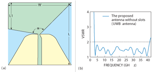
Figure 1 Geometry (a) and simulated VSWR results (b) of the proposed UWB antenna without slots.
The Proposed Antenna Structure and Design
UWB Antenna Design
Figure 1 shows the geometry and configuration of the proposed antenna without slots, which is a UWB antenna fed by a 50 Ω microstrip feed line. The length L (25 mm) and the width W (25 mm) are the dimensions of the dielectric substrate. L1 is the length of the patch, which is 10.4 mm. The most important parameter affecting the performance of the proposed antenna is the apex angle α, which is given by:
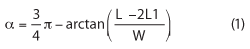
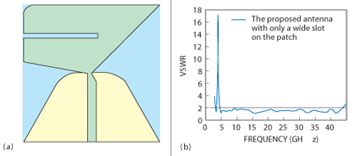
Figure 2 Geometry (a) and simulated VSWR results (b) for the proposed antenna with only a wide slot.
The tapered microstrip line at the connection between the feed line and the patch is used for broadband matching of the antenna to the 50 Ω microstrip line. The width and length of the 50 Ω microstrip line are 1.5 and 10.9 mm, respectively. The arcs at the edges of the patch and the ground plane are used for reducing the radiation loss and the difficulties of fabrication. The proposed antenna is printed on a FR4 substrate with a thickness of 0.8 mm, a relative permittivity of 4.4 and a loss tangent tan δ = 0.02. The simulated VSWR results of the proposed UWB antenna show that the impedance bandwidth (VSWR < 2) is from 2.9 to 41 GHz.
Figure 3 Geometry (a) and simulated VSWR results (b) of the proposed antenna with only a narrow slot in the ground plane.
Single Band-Notched UWB Antenna Design
To reduce the interference from WiMAX or WLAN applications, the band-notched function is desirable in the UWB system. Figures 2, 3 and 4 show the geometry and configuration of the proposed antennas, with a filtering property operating in the 3.2 to 3.9 GHz, 5.2 to 5.9 GHz and 5.14 to 5.94 GHz bands, respectively.
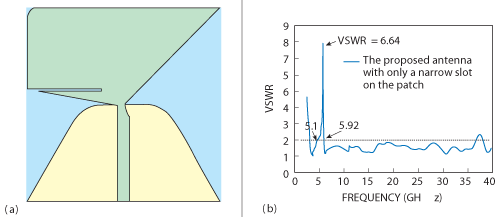
Figure 4 Geometry (a) and simulated VSWR results (b) of the proposed antenna with only a narrow slot on the patch.
By etching a straight slot in the patch or the ground plane of a UWB antenna, a frequency band notch is created. Note that when the band-notched design is applied to the UWB antenna, there is no retuning work required for the previously determined dimensions. Generally speaking, the design concept of the notch function is to adjust the total length of the straight slot in accordance with Equation 2. The wide slot etched in the patch shown in Figure 2, whose length and width are 13.8 and 0.8 mm respectively, is used to obtain the desired notched band from 3.2 to 3.9 GHz so that the proposed antenna cannot interfere with WiMAX applications. The narrow slot etched in the ground plane, shown in Figure 3, whose length and width are 8.4 and 0.2 mm, respectively, is used to obtain the desired notched band from 5.2 to 5.9 GHz and the narrow slot etched in the patch shown in Figure 4, whose length and width are 9.6 and 0.25 mm, respectively, is used to obtain the desired notched band from 5.14 to 5.94 GHz, so that the proposed antenna cannot interfere with WLAN applications. Note that the bandwidth is smaller when adding a narrow slot on the patch; the reason is that the narrow slot and the wide slot are so close that they interfere with each other. The notched frequency, given the dimensions of the band-notched feature, can be postulated as:
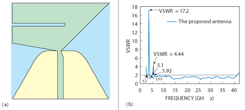
Figure 5 Geometry (a) and simulated VSWR results (b) of the proposed antenna.
Dual Band-Notched Antenna Design
To further the study of band-notched antennas and to reduce the interference from the existing bands, a dual band-notched function is desirable in a UWB system. Figures 5 and 6 show the geometry and configuration of the proposed dual band-notched antenna and the modified structure of the proposed antenna, respectively. From the VSWR results, it can be seen that the bandwidth of the UWB system is hardly affected by the slots and the bandwidth of the low frequency band-notched antenna formed by only a wide slot and the bandwidth of the high frequency band-notched antenna formed by only a narrow slot do not interfere with each other.
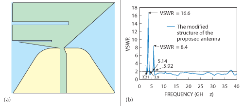
Figure 6 Geometry (a) and simulated VSWR results (b) of the modified structure of the proposed antenna.
Results and Analysis
The dual band-notched UWB antenna was simulated and optimized using CST software. Shown in Figure 7 are prototypes of the antenna and the modified structure of the proposed antenna. As shown in Figure 8, the simulated and measured results show relatively good agreement. The measurement shows that in the WiMAX band (3.2 to 3.9 GHz), the VSWR is greater than 2 and the center frequency of the notched band is approximately 3.55 GHz, while in the WLAN band (4.8 to 5.9 GHz), the VSWR is greater than 2 and the center frequency is approximately 5.35 GHz and in the 5.14 to 5.94 GHz band, the VSWR is greater than 2 and the center frequency is approximately 5.54 GHz for WLAN applications. The simulated radiation patterns at 3.1, 10.6 and 36 GHz are shown in Figures 9 and 10. The antennas give a nearly omnidirectional radiation pattern in the H-plane. The antennas’ simulated gains in the entire operating band are shown in Figure 11. As desired, two sharp gains decrease, are in the vicinity of 3.55 and 5.6 GHz, and the gains are stable in the entire operating band.
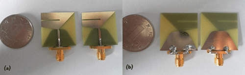
Figure 7 Photographs of the proposed and modified structure of the proposed antennas: front side (a) and back side (b).
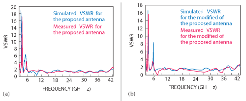
Figure 8 Simulated and measured VSWR results of the proposed antenna (a) and the modified structure of the proposed antenna (b).
Conclusion
A simple and compact ultra-wideband printed monopole antenna with dual band-notches and the modified structure of the antenna are proposed in this article. Using a monopole configuration, the antenna dimensions were optimized to gain the best VSWR response throughout the UWB frequency band. By embedding two slots in the antennas, dual band-notches are created, which avoid interference with existing WiMAX and WLAN operating bands and measurement results show that the designed antennas satisfy the UWB design goals very well.
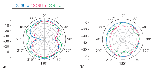
Figure 9 Radiation patterns on E-plane (a) and H-plane (b) for the proposed antenna.
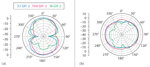
Figure 10 Radiation patterns on E-plane (a) and H-plane (b) for the modified structure of the proposed antenna.
Acknowledgments
This work was supported by the National Natural Science Foundation of China (No. 61172115 and No. 60872029), the High-Tech Research and Development Program of China (No. 2008AA01Z206), the Aeronautics Foundation of China (No. 20100180003), and the Fundamental Research Funds for the Central Universities (No. ZYGX 2009J037).
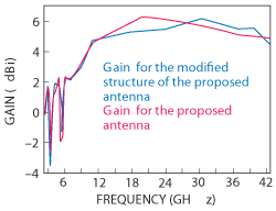
Figure 11 Gains of the proposed and modified structure of the proposed antennas.
References
- “First Report and Order in the Matter of Revision of Part 15 of the Commission’s Rules Regarding Ultra-Wideband Transmission Systems,” Released by Federal Communications Commission, ET-Docket 98-153, 2002.
- Q.X. Chu and Y.Y. Yang, “3.5/5.5 GHz Dual Band-notch Ultra-wideband Antenna,” Electronics Letters, Vol. 44, No. 3, January 31, 2008, pp. 172-174.
- X.J. Liao, H.C. Yang, N. Han and Y. Li, “Aperture UWB Antenna with Triple band-notched Characteristics,” Electronics Letters, Vol. 47, No. 2, January 2011, pp. 77-79.
- C.Y. Huang, S.A. Huang and C.F. Yang, “Band-notched Ultra-wideband Circular Slot Antenna with Inverted C-shaped Parasitic Strip,” Electronics Letters, Vol. 44, No. 15, July 17, 2008, pp. 891-892.
- H.H. Xie, Y.C. Jiao, Z. Zhang and Y. Song, “Band-notched Ultra-wideband Monopole Antenna Using Coupled Resonator,” Electronics Letters, Vol. 46, No. 16, August 5, 2010, pp. 1099-1100.
- R. Gayathri, T.U. Jisney, D.D. Krishna, M. Gopikrishna, and C.K. Aanandan, “Band-notched Inverted-cone Monopole Antenna for Compact UWB Systems,” Electronics Letters, Vol. 44, No. 20, September 25, 2008, pp. 1170-1171.
- M. Ojaroudi, S. Yazdanifard, N. Ojaroudi and R.A. Sadeghzadeh, “Band-notched Small Square-ring Antenna with a Pair of T-Shaped Strips Protruded Inside the Square Ring for UWB Applications,” IEEE Antennas and Wireless Propagation Letters, Vol. 10, 2011, pp. 227-230.
- J. Kim, C.S. Cho and J.W. Lee, “5.2 GHz Notched Ultra-wideband Antenna Using Slot-type SRR,” Electronics Letters, Vol. 42, No. 6, March 16, 2006, pp. 315-316.