The power handling capability for microwave filters has always been an important issue, and with the introduction of new spectrum efficient wireless systems, with large crest factors and stringent filtering demands, the ability to accurately predict the power handling capacity of a filter is as relevant as ever. When breakdown occurs in a filter, the surface is damaged and the interior gets contaminated with impurities, which often has the effect of decreasing the power handling capability of the filter as well as increasing the losses. Breakdown is therefore most often a destructive event, which leads to replacement of the filter.
Some simple waveguide filters may be analyzed for power handling using simple mathematical expressions, but generally this is not the case and 3D EM simulators therefore often have to be used for that purpose. For example, in order to power analyze a coaxial cavity filter with a 3D simulator, all couplings and tuning screw positions have to be optimized until the right filter characteristic is achieved. If the filter has more than just a few resonators, the task of obtaining a ‘nice’ filter characteristic will most often be an extremely time consuming matter – if possible at all.
In this article, a detailed step by step approach is presented for accurate power handling analysis of microwave filters – based on 3D EM analysis (HFSS in this case) on a single cavity plus knowledge about the filter obtained through circuit analysis (CMS). This approach leads to accurate results, even for complex filters, using a fraction of the time needed for a full 3D simulation on the actual filter itself. The analysis follows the methods outlined by other authors.1,2

Figure 1 HFSS model of filter to be analyzed for power handling capability.
Procedure for the Analysis
When a filter is designed and analyzed for power handling, the procedure can be broken down in the following eight steps:
- Synthesis of filter characteristic and coupling matrix based on simple lumped circuit models – or equivalent.
- Calculation of stored energies based on simple model.
- HFSS design of a single cavity so that it fulfils frequency and unloaded Q requirements.
- HFSS Eigen value simulation on the designed cavity. The stored energy is calculated using the HFSS Fields Calculator.
- The calculated stored energy is used to find a scale factor which, when applied to the source, gives a stored energy in the cavity equal to 1 nJ.
- The scale factor is applied via the “Edit Sources” functionality in HFSS and a Field Plot is generated. The peak E-field value is noted.
- The relation between stored energy and E-field is now established for the cavity in question. This relation is used together with the stored energy – previously calculated for each resonator in the filter (step 2) – to get the maximum E-field strength, which can occur in the filter.
-
This E-field value is compared to the breakdown threshold for air in order to validate the power handling capability of the filter.
All the above points will be dealt with, in detail, in the following.
Power Handling Analysis
To demonstrate the different steps outlined above, a coaxial cavity filter, for which a design already exists,3 will be used. A HFSS model of the filter is shown in Figure 1.
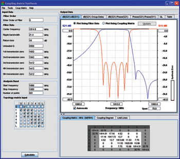
Figure 2 CMS synthesized filter characteristics.
Example Filter (Steps 1 & 2)
The filter has been synthesized using the Filter and Coupling Matrix Synthesis tool (CMS) from Guided Wave Technology.4 This tool uses coupling matrix synthesis techniques,5,6 for deriving a suitable topology and corresponding coupling matrix. The transformation of the coupling matrix into a physical filter may follow different paths, some of which have been described,3,7 but here, this subject will not be dealt with further.
The main parameters of the example filter are:
- Center frequency: 1915 MHz
- Ripple bandwidth: 20 MHz
- Return loss: 18 dB
- Transmission zero 1: 1932 MHz (x-coupling between resonator 3 & 5)
- Transmission zero 2: 1942 MHz (x-coupling between resonator 1 & 3)
The CMS synthesized filter characteristic and resulting coupling matrix are shown in Figure 2. The filter has been designed using the technique outlined by one of the authors.3 Therefore, all main- and x-coupling apertures have dimensions, which implement the coupling matrix also shown. The filter characteristics obtained through CMS are equivalent to the results one would get with a circuit simulator on lumped element models. The results are therefore most accurate for narrow band filters with relative bandwidths less than 10 percent.
Since the topic of this article is to investigate how accurate power handling can be predicted through simple analysis, the CMS model has been adjusted slightly to fit with the HFSS model. It is seen from Figure 3 that it is possible to get an almost 100 percent match between the two models.
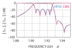
Figure 3 CMS and HFSS characteristics.

Figure 4 Stored energy levels for each resonator in the example filter.
In order to calculate the power handling of the final filter, one needs to know the stored energy level of each individual resonator. In CMS, this information is available in the QL (Loaded Q) pane, whose content is shown in Figure 4. It is seen here that the highest stored energy level (72 nJ/W) is found at resonator 2, just outside the passband (1926.2 MHz). At other frequencies, the situation may be very different as seen from the figure. Across the passband, resonators 2, 3 and 4 have, in turn, the highest stored energy levels. Loaded Q is an equivalent way of describing the same as stored energy.
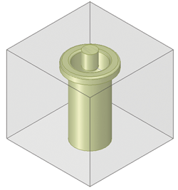
Figure 5 Single resonator HFSS model.
The power handling capability of the filter will be analyzed at the center frequency (1915 MHz). The highest stored energy level at this frequency, 12.2 nJ/W, is found in resonator 3. It will be assumed for a start that a perfect match exists between the filter and the load (for example an antenna). This is obtained by entering a high dB value in the return loss field in the plot. In reality, a perfect match is not possible and a more realistic value would be 15 to 20 dB, but this will be dealt with later. In the following, a perfect match is assumed. Steps 1 and 2 of the procedure outlined previously have now been completed.
Single Cavity HFSS Simulation (Step 3)
In order to find the relationship between stored energy and peak E-field in the filter, a simple HFSS model of a single resonator is made. The model should contain all relevant details of the resonator – especially near the top where the E-field is strongest. The model is shown in Figure 5.
The single resonator model has the same height and layout as the resonators in the example filter. The cavity is a simple square cavity with a base area tuned to give an overall resonance frequency close to fc (1915 MHz – this is done fast in a few trials with the Eigen mode solver). The height of the cavity is identical to the example filter cavity height.
Calculating Stored Energy (Step 4)
A HFSS Eigen mode simulation is now performed on this resonator. Since the highest field strength is restricted to a small area around the edge of the tuning screw, it is important that the mesh is fine enough for accurate results. To ensure accuracy, the calculated stored energy can be used as convergence criteria in the adaptive mesh refinement.
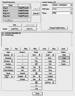
Figure 6 HFSS fields calculator.
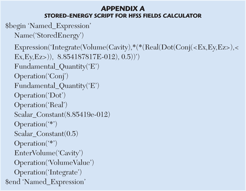
When the simulation is done, post processing must be performed, using the Fields Calculator in HFSS to find the stored energy. Ansoft has made a collection of recipes,8 in which one can find instructions about how to calculate the peak electrical energy in a volume. In Appendix A, the script necessary for calculating the stored energy is listed. These few lines may be written and stored in a text file of type “.clc” and loaded into the field calculator. The “clc” file may also be downloaded from www.gwtsoft.com/Misc/StoredEnergy.zip.
When the fields calculator is started (in HFSS project ‘tree’: Right click on ‘Field Overlays’ and chose ‘Calculator’) the window shown in Figure 6 appears. Use the ‘Load From’ button to load the ‘StoredEnergy.clc’ script into the calculator – or write your own script using the built-in calculator functions.
Important: If you use the downloaded StoredEnergy scrip, it is important to note that this script assumes that the model consists of one single vacuum object with the name: Cavity. The resonator and tuning screw have been subtracted from the square cavity. The name of this vacuum object must match the name used in the script (that is ‘Cavity’). When the StoredEnergy script is successfully loaded into the calculator, it must be selected and made active by using the “Copy to stack” button. The stored energy can now be calculated by selecting the “Eval” button. In the present case one gets: WHFSS = 6.922E-21 J.
Normalization (Steps 5 & 6)
The next step is to use the just found stored energy to adjust the source excitation so that the stored energy in the cavity becomes 1 nJ. The reason for this is that the CMS generated stored energies use 1 nJ as reference (See Figure 4).
The following normalization/scaling constant is defined:
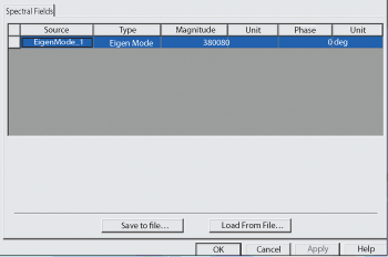
Figure 7 Insertion of normalized excitation in "Edit Sources" menu.
norm = sqrt(1 nJ/WHFSS) (1)
WHFSS is the stored energy just found by the fields calculator in HFSS.
One gets: norm = sqrt(1E-9/6.92E-21) = 380080. This voltage is inserted in the Magnitude field in the ‘Edit Sources’ menu (in HFSS project ‘tree’: Right click on ‘Field Overlays’ and choose ‘Edit Sources’) as shown in Figure 7. When the normalization is done, it can be verified that it has been done correctly by using the fields calculator again to find the stored energy, which should now give 1 nJ. With the excitation voltage properly scaled it is now time to plot the E-fields in the cavity. This is shown in Figure 8. The E-field strengths in the cavity can be read from the legend scale to the left in the figure.
Hint: Use the ‘ComplexMag_E’ function when plotting the E-field. This function displays the E-field at its maximum. A maximum E-field of 4.44E4 V/m is read. This value is obtained at the lower edge of the tuning screw. This E-field is what results from 1 nJ stored energy in this cavity.
Enorm,max = 4.44E4 V/m/√(nJ)
All information necessary for calculating the power handling capability of the final filter is now available.
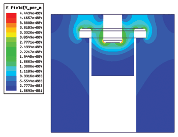
Figure 8 E-field plot in the cavity corresponding to a stored energy level of 1 nJ.
Hint: In Figure 8, the E-field has been plotted in a plane through the center of the resonator. This is a better approach than plotting the E-field in the whole cavity volume. Numerical ‘fluctuations’ may locally (that is in a single mesh cell) give E-field strengths above the ‘true’ max level. By mapping E-field in planes instead of volumes, the probability of hitting such a cell is very low. To validate the result, one can rotate the plane 90° to see that approximately the same max E-field is obtained.
Power Handling Capability of Example Filter (Steps 7 & 8)
With the maximum normalized E-field in a single cavity now determined, the simple equation below (Eq. 2) is used to find the actual maximum E-fields in resonator ‘i’ of the example filter1:
Emax,i = Enorm,max sqrt(P*WCMS,i) (2)
Emax,i is the maximum E-field strength at the ith resonator.
Enorm,max is the maximum normalized E-field found by a single cavity HFSS simulation.
P is the input power to the filter in Watt.
WCMS,i is the stored energy of the ith resonator found from the CMS model.
Please note that there is a typing error in the expression given in Ref. 1, which has been corrected in Equation 2.
From the CMS stored-energy simulation in Figure 4, it was found that the maximum stored energy at 1915 MHz was in resonator 3.
WCMS,2 = 12.2 nJ/W
It was also previously found that
Enorm,max = 4.44E4 V/m
Assuming an input power P = 20 W, one then gets
Emax = 4.44E4 sqrt(20*12.2) = 0.69 MV/m
which is the maximum E-field strength in the filter at 1915 MHz for 20 W input.
As a rule of thumb, the breakdown field-strength at 1 atmosphere for microwave signals is 2.3 MV/m.1
For 20 W input to the filter, a comfortable margin exists to the breakdown limit in resonator 3 at 1915 MHz. Normally it is good practice to have a factor two safety margin to the breakdown limit. Rewriting Eq. 2 gives:
P = (Emax,i / Enorm,max)2 / WCMS,i (3)
If Emax,i is replaced in Equation 3 by the breakdown field strength at normal pressure (2.3 MV/m), the following expression for the breakdown input power appears:
PBD = (2.3E6 / Enorm,max)2 / WCMS,i (4)
If the above used values for Enorm,max and WCMS,i are inserted one gets:
PBD = (2.3E6 / 4.44E4)2 /12.2 = 220 W
which is the threshold input power for breakdown in this filter at 1915 MHz
At other frequencies, the situation may be quite different. At a little above the passband (1926.2 MHz), it is seen that resonator 2 is the limiting resonator with a stored energy level equal to 72.1 nJ/W. The breakdown power is PBD = (2.3E6/4.44E4)2/72.1 = 37 W, which is six times lower power-handling capacity compared to the center frequency.
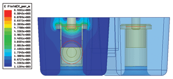
Figure 9 E-field strength in a plane through resonators for 20 W input power.
Comparison with a Full HFSS Filter Simulation
To validate the above results, a breakdown analysis has been conducted on the complete filter whose filter characteristic has been optimized in HFSS to give the result shown in Figure 3. From Figure 4, it is known that at the center frequency the highest stored energy for the complete filter is found in resonator 3. The field strengths are therefore plotted in a plane through the center of this resonator, as shown in Figure 9, with the power at the input port set at 20 W. It is seen that the field analysis of the complete filter gives a max E field equal to 0.69 MV/m. From the simple analysis conducted previously, the max E field was found to be 0.69 MV/m. Identical results have therefore been obtained – but with the simple method, the time and computer resources used for the job, have been at least an order of magnitude lower compared to the HFSS treatment of the full problem.
Other Factors with Influence on Power Handling
Load Mismatch
It was mentioned in the example filter section that the load return loss has also an influence on the power handling capacity of a filter. If power is reflected at the load, this leads to standing waves in the filter, which may severely decrease the power capacity of the filter. If the reflection coefficient at the load is ρ, the worst case level of stored energy in the filter increases by a factor (1+ρ)2.
In CMS, it is possible to enter the actual load reflection coefficient when calculating stored energies in a filter (see Figure 4). In the previous sections, it was assumed that a perfect match existed between filter and load. If instead a 15 dB return loss is assumed, the breakdown power will decrease from 220 W to 149 W at the center frequency. Compared to a reflection free connection – the 15 dB load return loss will, in the worst case, reduce the power handling capability of the filter by a third. Whether or not a worst case situation appears is dependent on the actual phase condition of the connection between filter and load. Often this connection is difficult to control and one should therefore assure that the filter is capable of handling the worst case situation.
Pressure, Temperature and Moisture
Low pressure, high temperature and humidity will also decrease the power handling capacity of a filter. Of these, especially pressure and temperature may give rise to problems under certain conditions. Here, these issues will not be dealt with, but it shall only be mentioned that pressure must be considered for equipment intended for high altitudes, aeronautical applications or space: The power handling capability may well be reduced by a factor of 100 when subjected to the low pressure environment at for example 10 km altitude. An overview of these factors can be found in the literature.9
Conclusion
In this article, a step-by-step approach has been described, which allows filter engineers to make accurate power handling analysis of microwave filters with minimum use of computer resources and time. To demonstrate the method, a circuit model has been combined with 3D electromagnetic simulations on a single resonator, whereby the power handling capacity has been determined for a five pole coaxial cavity filter with two cross couplings. The method determines the peak electrical field strength in the filter – and the breakdown power.
To verify the results, full 3D simulations on the complete filter have also been carried out. It has here been demonstrated that the simple method gives near identical results to full 3D simulations – but with a time consumption which may well be an order of magnitude lower than 3D simulations on the complete filter.
References
- M. Yu, “Power-Handling Capability for RF Filters,” IEEE Microwave Magazine, Vol. 8, No. 5, October 2007, pp. 88-97.
- C. Wang and K.A. Zaki, “Analysis of Power Handling Capacity of Band Pass Filters,” 2001 IEEE MTT-S International Microwave Symposium Digest, Vol. 3, pp. 1611-1614.
- A. Edquist, “Filter Design and Ansoft Tools,” www.ansoft.com/workshops/hfssinfoday/FilterDesign_and_HFSS_HO.pdf.
- CMS Software: “Filter and Coupling Matrix Synthesis,” Guided Wave Technology ApS, www.gwtsoft.com.
- R.J. Cameron, “Advanced Coupling Matrix Synthesis Techniques for Microwave Filters,” IEEE Transactions on Microwave Theory and Techniques, Vol. 51, No. 1, January 2003, pp. 1-10.
- R.J. Cameron, “General Coupling Matrix Synthesis Methods for Chebyshev Filtering Functions,” IEEE Transactions on Microwave Theory and Techniques, Vol. 47, No. 4, April 1999, pp. 433-442.
- M. Hagensen, “Narrowband Microwave Bandpass Filter Design by Coupling Matrix Synthesis,” Microwave Journal, Vol. 53, No. 4, April 2010, pp. 218-226.
- Ansoft HFSS Field Calculator Cookbook. “A Brief Primer and Collection of Step-by-step Calculator Recipes for Use in HFSS Fields Post-processing.”
- T. Wilsey and G. Meddaugh, “Equations Aid Breakdown-Free Component Design,” Microwaves & RF, November 1, 1991, pp. 79-91.
