
Crane Aerospace & Electronics, Microwave Solutions, has recently introduced a new high-performance switch matrix covering L-Band aimed at satellite communications ground station applications. This system provides new breakthroughs in signal fidelity preservation and built-in-test features allowing for critical communications to be preserved. It offers a flexible architecture, which can be configured from 12 antenna ports and 48 modem ports to as large as 24 antenna ports to 192 modem ports, and can be upgraded in the field. There are separate transmit and receive units that pass the signals to and from the modems and frequency converters.
The receive switch matrix is built around a classic architecture with power dividers being fed from each input, feeding multi-throw switches to select the feed to the appropriate output. This technique results in what is called a Full-Fan-Out architecture. Full-Fan-Out refers to the fact that one input signal can drive any, some or all outputs simultaneously without loss of signal fidelity. Losses from the power division are overcome through the use of custom-designed amplifiers. To ensure that proper performance is achieved, the amplifiers selected for this application have critical band flatness, noise figure, intercept point and compression performance specifications. A simple functional block diagram of the configuration is shown in Figure 1.
Components used in this system design, due to the critical performance required for the unit, were created within Crane Aerospace & Electronics. Power dividers in two-, four- and 24-way configurations are utilized. These are built using a traditional Wilkinson structure with stripline technology as the basis. Excellent frequency flatness and VSWR performance is achieved. Frequency slope compensating equalizers are included to insure that the entire design meets the overall flatness performance window.
RF switch cards were designed and also manufactured internally by Crane Aerospace & Electronics. These are based on GaAs PHEMT technology for the switch elements. Utilization of a well-matched, terminated switch design ensures that the prescribed isolation, power handling and intercept performance is achieved. Control to the switch assemblies is achieved using a parallel data bus, which is addressable for each card in the switch assembly.
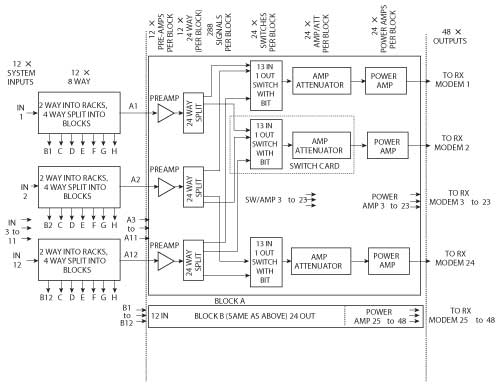
Figure 1 L-Band switch matrix block diagram.
To achieve the ultimate configuration of the system required, the components have been integrated into 12×24 matrix building blocks. These are rack-mount, fully integrated assemblies containing the amplifiers, power dividers and switch cards along with digital control and DC power supply regulation. To achieve a 12×48 switch matrix, two of these 12×24 matrix blocks are used along with an input power divider (two-way) assembly, splitting the 12 inputs to the two switch block assemblies. Their outputs directly drive the user’s system.
An advanced built-in-test system is included in the system. Under command of the system controller are signal generators and receivers, available on each of the signal paths, which pass through the system and test for RF continuity from input to output. If signals are not detected at certain points in the prescribed path, the internal controller can provide trouble-shooting information to service personnel indicating which assemblies are the most likely failure points. This process helps with the ability to rapidly service the system and get it back to full operation following a failure.
Another feature to enhance system reliability is the incorporated redundant power supply system. Each rack of equipment contains duplicate power supplies with a sophisticated summing and monitoring system. The system can operate on one of these power supplies. Should one power supply fail, the system will continue operating on the single supply. The internal diagnostics provide an alarm indication through the command controller. The system operator can remove the failed power supply and replace it with a new one without taking the system off-line.
Unit control is achieved using a single-board PC architecture. The controller receives commands through the TCP/IP Ethernet. These commands are then executed by selecting the appropriate switches to connect the signals from the desired input to prescribed output. Additional support commands, such as status polling, configuration information, etc., are available in response to a command. A front panel character display and keypad also allow local control and configuration.
A companion to the receive matrix, a transmit path matrix, is also provided. This system operates in an opposite manner of the receive system described above. In this case, multiple modems are connected to the desired number of upconverters. This matrix combines these signals so that they are available within the IF bandwidth to drive the upconverter. Individual control of the modem signal level is provided so that no overdrive condition is experienced.
Crane Aerospace & Electronics,
Beverly, MA
(978) 524-7200,
www.craneae.com/mw,
mw@crane-eg.com.