
The Global Positioning System (GPS) is a worldwide satellite navigation system, which consists of a constellation of 24 satellites and their ground stations. GPS signals are specially coded satellite signals that can be processed in a GPS receiver. When receiving the signals from at least four satellites, a receiver can determine latitude, longitude, altitude, time and velocity of the receiver by measuring the travel time of a signal transmitted from each satellite.1,2,3 For a Standard Positioning Service (SPS), each satellite transmits the signal L1 (1575.42 MHz), which is modulated by the C/A (coarse/acquisition) code. The C/A code is a 1023 chip long pseudo-random number (PRN) sequence sent at a rate of 1023 megabits/sec.4,5,6
In a GPS receiver, the information is modulated with a pseudo-random noise (PRN) code. The used PN codes have an auto-correlation property only with a synchronized copy of itself.1 A receiver should generate a synchronized copy of the code and multiply it by the received signal. If the local code is perfectly synchronized, then its correlation with the original signal is maximum; otherwise, the correlation is very low. Synchronizing a GPS signal with the local code is called acquisition. Acquisition in a GPS system is used to calculate the code phase (or shift) and find the pseudo-range, which is used to calculate the position. Acquisition of the signal in GPS receivers is the most critical part, due to the required number of processing steps and long processing time. It is important to perform the acquisition as fast as possible in order for an auto-navigation system to be practical.1,7 There are two primary sources of trouble connected with slow acquisition. One of them is related to the large computation count in the search algorithm. This can be seen in the FFT-based convolution algorithm. While it is a fast search method, it requires the computation of two FFTs and one IFFT. These functions require a large number of multiplication and addition operations for the 1 ms data. Thus, the correlation function takes most of the computation time in the GPS receiver.8 Investigating different methods for convolution (or correlation) that require less computation time, therefore, is an important research topic.9,10
Furthermore, since the first GPS satellite was commissioned in 1977,1,2 the research community has spent enormous effort to increase the accuracy of the system. The effect of multipath, however, is still a major stumbling block that reduces the accuracy of the system.2,11 In this article, various acquisition schemes are investigated for rapid GPS signal acquisition over multipath Rayleigh fading channels.
Multipath Characteristics
The term multipath is derived from the fact that a signal transmitted from a GPS satellite can follow a ‘multiple’ number of propagation ‘paths’ to the receiving antenna. This is possible because the signal can be reflected back to the antenna off surrounding objects, including the earth’s surface. Figure 1 illustrates this phenomena for one reflected signal.
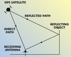
Fig. 1 Multipath signals (direct and reflected).
Some important characteristics of multipath are as follows:12
- A multipath signal will always arrive after the direct path signal because it must travel a longer propagation path.
- A multipath signal will normally be weaker than the direct path signal since some signal power will be lost from the reflection. It can be stronger if the direct path signal is hindered in some way.
- If the delay of a multipath is less than two PRN code chip lengths, the internally generated receiver signal will partially correlate with it. If the delay is greater than two chips, the correlation power will be negligible.
Channel Model
A popular channel model for the terrestrial personal and mobile communication environment is given by the impulse response
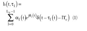
where
LP = path number
τl(t) = path delay
αl(t) = Rayleigh fading over (0,2π) of the l-th path at time t
θl(t) = uniform random phase over (0,2π) of the l-th path at time t
δ(t) = Dirac pulse
Tc = chip duration
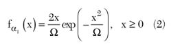
In the model used, the channel is frequency-selective with three paths (LP = 3). A widely accepted model for a frequency-selective channel is a finite-length tapped delay line with a tap spacing of one chip,13 as shown in Figure 2, where the LP tap weights (α1) are assumed to be independent identically distributed (i.i.d.) Rayleigh random variables with a probability density function (pdf) given by13
where E[αl2] = W, and the phases (θl) are assumed i.i.d. random variables uniformly distributed in (0,2π). y(t) is given by
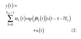
where
τ = code phase (delay) to be estimated
n(t) = AWGN with one-side power spectral density of N0 watts/Hz
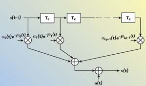
Fig. 2 Tapped delay line model of the frequency-selective channel.
Figure 3 shows an example of Rayleigh fading pace for one channel path with averaged fading A0 = –1.5 dB.
Fig. 3 Example of a Rayleigh fading (A0 = -1.5 dB).
Signal Acquisition
In a GPS system, when the received signal is multiplied by a synchronized version of the PRN code, the signal is despread. Its power increases over the noise floor. Therefore, it appears as a correlation peak. In order for a receiver to synchronize to the received signal, however, an initial estimation of the code and carrier is calculated. The acquisition process is the first process required by the GPS receiver. The acquisition process conducts a three-dimensional search. The three elements (or search bins) are the available C/A code, the code phase and the carrier frequency offset. If a GPS receiver is assumed to know which satellite code it is searching for, then a 2-D search is required.1 One dimension is the code phase in the range of 1023 chips. The code phase resolution is half of a code chip. This resolution is required since the correlation peak is considered a true peak only if the code phase is within a half chip. The second search dimension is for the carrier frequency. Its range is ±10 kHz centered at an intermediate frequency (IF) of 1.25 MHz. The resolution of the carrier frequency is typically 667 Hz for 1 ms integration.14 Searching with 500 Hz steps can be used.15
In a GPS receiver this search detects the correlation peak and compares it to a certain threshold to determine whether a satellite was detected or not. When a satellite is detected, the auto-correlation result provides a rough estimation of the code phase and the carrier frequency. The acquisition process should provide this data. However, if the search process does not locate a peak that passed the detection threshold, a satellite is considered “not-acquired” and the search continues. The search space must cover the full range of uncertainty in the code and Doppler offset. Because the C/A code is fairly short (1 ms), the range space will typically include all possible code offset values. The selection of a path through the search space is a function of the vehicle dynamics and requirements for acquisition speed and reliability. Typically, the Doppler is set to the expected value and the code is searched over all possible delays. If this fails, the search is continued in the next Doppler bin, with the sequence of bins alternating above and below the starting Doppler (this is a serial acquisition algorithm principle). Figure 4 depicts the acquisition uncertainty region.
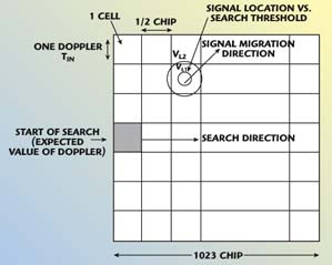
Fig. 4 Acquisition uncertainty region1.
Serial Search Algorithm
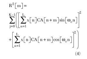
Serial search is the simplest and most frequently used acquisition algorithm. The principle of the code acquisition system working in multipath Rayleigh fading is represented in Figure 5, where, since the phase of the received signal is random, a noncoherent correlator is used. First the digital IF, x[n], is multiplied by the replicated CA code, CA[n+m]. Here n represents the nth sample and m represents the number of samples the replicated CA code is phase shifted. Since the sampling rate is 5 MHz, the length, L, of one C/A code period is 5000 samples nominally.
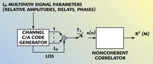
Fig. 5 Code acquisition in multipath channel.
After the code removal, the in-phase (I) and quadrature (Q) components are generated. The I and Q components are accumulated for one code period. The accumulated sum is squared. The next K correlations are accumulated to produce an averaged correlation point. If the correlation point is larger than a certain thresh-
old it is assumed that the satellite is acquired. The correlation is approximated by the discrete sum
where
ωc = radian frequency
Usually, when serial search is performed, the code phase is incremented by one-half chip when one code phase has been tested (the reason for choosing a one-half chip increment is obvious when examining the autocorrelation function of one typical C/A code). Thus, there are 2 ¥ 1023 = 2046 code phases that must be tested.
Complicating things, the Doppler effects on the carrier must be taken into account. For a stationary receiver, it is common to assume a ±10 kHz Doppler offset on the carrier. The acquisition process for each code period is stepped in the Doppler range in 500 Hz frequency increments. Choosing 500 Hz steps is a compromise in accuracy and speed. If the step was 1 kHz, there would be less frequency bins to test, but with the possibility that the residual carrier of the I and Q components can cancel out the correlation, since 1 kHz corresponds to the code period of 1 ms. The Matlab implementation utilizes an exhaustive search, that is, all possible combinations of code phases and Doppler offsets are tested and a correlation matrix is generated. A real GPS receiver would set a threshold and transition to tracking when the threshold is crossed.
The disadvantage of this search is that it might necessitate exploring all of the combinations of the 2-D search plane serially. Thus, it tests 2046 half chips on the code phase dimension for 41 carrier frequency search steps (bin resolution = ±500 Hz). This means searching approximately 80,000 combinations, which is time consuming. The acquisition process time is shortened when the search dimensions can be searched in parallel.
FFT Search Algorithm
The acquisition process time is shortened when the linear search algorithm can be performed as illustrated in Figure 6. Here, 5000 samples of the received data x[n], digitized at IF, are correlated with the replica code, CA[n+m], by circularly shifting the replica code. This resembles the circular convolution and may be expressed as
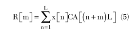
The circular convolution is a multiplication in the frequency domain. In fact it can be written as
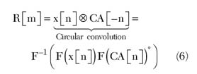
where the discrete Fourier transform (DFT) and its inverse are used to calculate R. This can be adopted for the acquisition of GPS signals as shown.
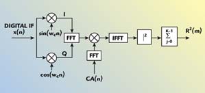
Fig. 6 Noncoherent correlator in frequency domain.
In this algorithm, two 5000-point FFTs and one 5000-point IFFT are required to implement the C/A code correlator. The size of the FFT is not a power of two, however, so it will be very difficult to implement since it requires a mixed-radix algorithm that includes non-power-of-two FFTs.8 The use of smaller FFTs is needed to map the acquisition process. One suggested method for solving this problem is the acquisition of the C/A code using averaging correlators. It uses FFTs with a similar size of C/A code — 1023 is used instead of 5000-point FFTs.16
Averaging-correlation Algorithm
The FFT search algorithm requires the C/A code to be up-sampled to 5000 points to match the received GPS signal, the required FFT size needs to be 5000. Similarly, when an opposite approach is carried out, the FFT size is smaller. Thus, if the incoming sampled GPS signal is down-sampled from 5000 to 1023 points then the same FFT-based correlator can be applied, but with a FFT size of only 1023. The correlation will be carried out by frequency transforming the 1023 averaged (or down-sampled) GPS signal using 1023-points FFT. This is performed on both the in-phase and the quadrature-phase by considering the in-phase values as the real input components, while the quadrature-phase values are used as the imaginary input components. First, apply 1023-points FFT to the local code and perform the conjugate operation to the FFT output. The next step is to multiply the complex outputs of the FFTs. The results are then changed back to the time domain using 1023 points inverse fast Fourier transform (IFFT).
In order to compute the correlation functions in 1023-points FFT block, the method called “averaging correlation”16 is introduced here. The received signal needs to be reduced back to 1023 chips per millisecond by averaging consecutive 4 or 5 points into one chip. The averaged chip is similar to a chip of C/A code. Since the signal cannot be observed in the form of square waves, there is not enough information to determine which four or five points should be grouped together and averaged, unless there can be an approach to know the relative position of the samples and the chips. However, this relative position can be found from several attempts of averaging with different assumption of the relative position.17
Among the first consecutive five samples, one must be the first sample of a chip, since no chip contains more than five samples. Assuming this sample is regarded as the beginning of the first chip, the relative position of the 1023 chips and all the samples can be determined and the chips can be recovered completely. Thus, five averaged sequences, each containing 1023 chips, are generated and their correlation functions with local C/A code are computed, respectively. Knowing the correlation peak indicates the signal energy, the sequence with the largest correlation peak is chosen as the one used for acquisition. With the five averaged sequences and 1023 chips C/A code, the correlation must be performed five times. Notice that five times 1023 FFT is still much cheaper than 5000 FFT performed once, in hardware or just software simulation in Matlab. A block diagram of the averaging correlator-based acquisition is shown in Figure 7.15
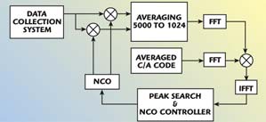
Fig. 7 Acquisition using an averaging correlator.
As one will see in the numerical results, the averaging correlation can work as well as the 5000 FFT method in signal acquisition. It is a very fast code acquisition algorithm but is more sensitive to the noise variance, as will be shown later.
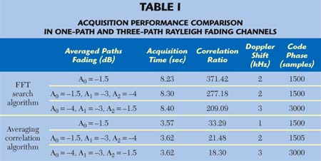
Numerical and Simulation Results
In this section, the acquisition performance of the FFT and the averaging-correlation algorithms in one-path and multipath Rayleigh fading channels are compared. The results are shown in Table 1.
Consider first the case of a one-path Rayleigh fading channel with the averaged path fading A0 = –1.5 dB. Figure 8 presents a small set of correlation matrix when satellite 19 is searched for (in the Matlab simulation) over a one-path Rayleigh fading channel. The averaging-correlation algorithm is very fast but very sensitive to noise.
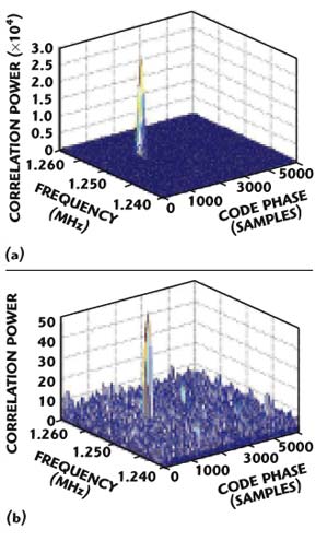
Fig. 8 Correlation matrix for satellite 19 in one-path Rayleigh fading channel (A0 = -1.5 dB); (a) FFT search and (b) averaging-correlation algorithm.
Consider next a multipath Rayleigh fading channel, using the parameters A0 = –1.5 dB, A1 = –3 dB and A2 = –4 dB (averaged paths fading). Figure 9 presents the correlation matrix over a three-path Rayleigh fading channel. In this case, within one code period, there exist three correct cells in the time uncertainty region that can be accepted. The two algorithms can well detect the signal of the path characterized by the weakest fading (A0 = –1.5 dB). In a one-path Rayleigh fading channel, compared to a multipath Rayleigh fading channel, the effect that one-path is faded leads to the best result.
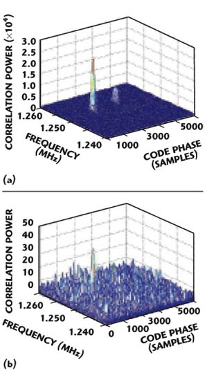
Fig. 9 Correlation matrix for satellite 19 in three-path Rayleigh fading channel (A0 = -1.5 dB, A1 = -3 dB, A2 = -4 dB); (a) FFT search and (b) averaging-correlation algorithm.
Finally, Figure 10 presents another case of a multipath Rayleigh fading channel but with the following parameters: A0 = –4 dB, A1 = –3 dB and A2 = –1.5 dB. Also, in this case, three correlation peaks are detected. As opposed to the previous case, however, the two algorithms well detect the signal of the path characterized by the averaged fading A2 = –1.5 dB (that is the weakest path fading).
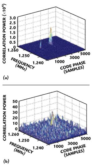
Fig. 10 Correlation matrix for satellite 19 in three-path Rayleigh fading channel (A0 = -4 dB, A1 = -3 dB, A2 = -1.5 dB); (a) FFT search and (b) averaging- correlation algorithm.
The averaging-correlation algorithm is noticeably faster than the FFT search algorithm in both cases of one-path and multipath Rayleigh fading channels. In the case of a multipath Rayleigh fading channel, the averaging-correlation algorithm could not detect the two other peaks that are characterized by the higher fading, because this algorithm is very sensitive to noise.
The effect of noise variance and Doppler shift on acquisition performance of both FFT search and averaging-correlation algorithms in AWGN and multipath Rayleigh fading (A0 = –1.5 dB, A1 = –3 dB and A2 = –4 dB) channels was also simulated. Figure 11 shows the effect of noise variance on the code phase shift. From the result, it can be seen that the FFT search algorithm in a multipath channel works very well, like the one in an AWGN channel until the noise variance reaches the value 0.6. The code phase is lost for higher values than 0.6. The averaging-correlation algorithm is more sensitive to the noise variance, in both AWGN and multipath Rayleigh fading channels. Figure 12 shows the effect of Doppler shift on the code phase. First, the averaging-correlation algorithm cannot find the accurate code phase shift in both AWGN and multipath Rayleigh fading channels. Second, in a Rayleigh fading channel, when the Doppler shift varies in the interval (–1 kHz, +1 kHz), the code acquisition fails for both FFT search and averaging-correlation algorithms.
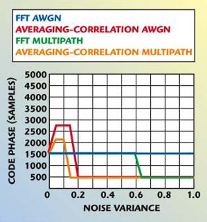
Fig. 11 Effect of noise variance.
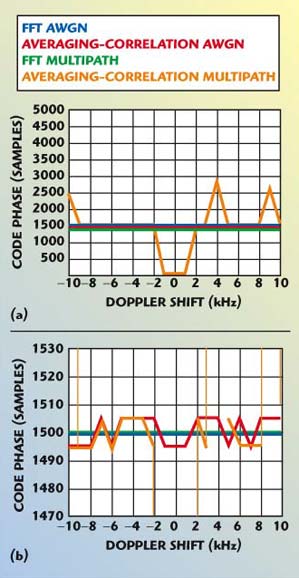
Fig. 12 Effect of Doppler shift; (a) full scale and (b) expanded scale.
Conclusion
In this article, a simple method for fast GPS signal acquisition is proposed in frequency-selective Rayleigh fading channels. This method, based on averaging correlation, is used to carry out the convolution operation with more speed and less complexity. The acquisition performance of the averaging-correlation algorithm was compared with that of the FFT search algorithm in one-path and multipath Rayleigh fading channels. The issues discussed include acquisition performance, noise variance and Doppler shift effects. From the results, it was found that the averaging-correlation algorithm is very fast but very sensitive to noise. Moreover, in a multipath Rayleigh fading channel, the path with weakest fading was detected more accurately. From the observation of the Doppler shift effect on the code phase, it was observed that in a Rayleigh fading channel, the code acquisition fails for both FFT search and averaging-correlation algorithms when the Doppler frequency varies in the interval delimited by the two values –1 kHz and +1 kHz.
References
- E.D. Kaplan, Ed., Understanding GPS: Principles and Applications, Artech House Inc., Norwood, MA, 1996.
- B.W. Parkinson and J.J. Spilker Jr., Eds., “Global Positioning System: Theory and Application, Volume 1,” American Institute of Astronautics, June 1996.
- J.B.Y. Tsui, Fundamentals of Global Positioning System Receivers: A Software Approach, John Wiley & Sons Inc., Somerset, NJ, 2000.
- M. Braasch and A. Van Dierendonck, “GPS Receiver Architectures and Measurements,” Proceedings of the IEEE, Vol. 87, No. 1, January 1999, pp. 48–64.
- ICD-GPS-200 (GPS Interface Control Document), GPS Joint Program Office (prepared by ARINC Research), July 1991.
- D. Djebouri and M. Djebbouri, “GPS Satellite Signal Synchronization,” Conférence Internationale sur les Systèmes de Télécommunications, d’Electronique Médicale et d’Automatique (CISTEMA’ 2003), Tlemcen, Algeria, 27–29 September 2003.
- A. Alaqeeli and J. Starzyk, “Hardware Implementation for Fast Convolution with a PN Code Using Field Programmable Gate Array,” Proceedings of the 33rd Southeastern Symposium on System Theory, Athens, OH, March 2001, pp. 197–201.
- S. Gunawardena, “Feasibility Study for Implementation of Global Positioning System Processing Techniques in Field Programmable Gate Arrays,” Master of Science Thesis, Ohio University, Athens, OH, November 2000.
- M. Djebbouri and D. Djebouri, “Robust GPS Satellite Signal Acquisition Using Wavelets,” accepted for publication in the International Journal of Wavelets, Multi-resolution and Information Processing (IJWMIP), 2004.
- M. Djebbouri and D. Djebouri, “Fast GPS Satellite Signal Acquisition,” Electronics Letters, October 1, 2003, pp. 1–12.
- B.M. Hannah, “Modelling and Simulation of GPS Multipath Propagation,” Doctoral Dissertation, Queensland University of Technology, Melbourne, Australia, March 2001.
- B.R. Townsend and P.C. Fenton, “A Practical Approach to the Reduction of Pseudo-range Multipath Errors in a L1 GPS Receiver,” ION GPS-94, Salt Lake City, UT, September 20–23, 1994.
- J.G. Proakis, Digital Communications, Third Edition, McGraw-Hill, New York, NY, 1995.
- K. Krumvieda, P. Madhani, J. Thomas, P. Axelrad, W. Kober, C. Heddings, P. Howe and J. Leonard, “A Complete IF Software GPS Receiver: A Tutorial About the Details,” 14th International Technical Meeting of the Satellite Division of the Institute of Navigation (ION GPS), Salt Palace Convention Center, Salt Lake City, UT, 11–14 September 2001.
- A. Alaqeeli Abdulqadir, “Global Positioning System Signal Acquisition and Tracking Using Field Programmable Gate Arrays,” Doctoral Dissertation, Ohio University, Athens, OH, November 2002.
- J. Starzyk and Z. Zhu, “Averaging Correlation for C/A Code Acquisition and Tracking in Frequency Domain,” MWSCS Conference, Fairborn, OH, August 2001.
- Z. Zhu, “Averaging Correlation for Weak Global Positioning System Signal Processing,” Master of Science Dissertation, Ohio State University, Columbus, OH, March 2002.