
In Part I of this article,1 a number of experimental results were presented, suggesting that interactions in arrays of tag antennas play an important role in determining when a UHF RFID tag can be read, even when no other scattering is present in the environment. How can these effects be understood and predicted? It is first helpful to verify that, given the measured antenna geometry and reasonable values for the impedance of the integrated circuit loads, the observed behavior can be numerically reproduced from expected electromagnetic interactions. Such a demonstration both validates the interpretation of the measured data and limits the scope of physical effects that need to be considered to those incorporated in the numerical model. Guided by the results of numerical modeling, an attempt was also made to formulate a quasi-analytic model that is less accurate but computationally much less demanding, and thus easier to implement and scale to large arrays and complex geometries.
Numerical Simulations
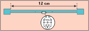
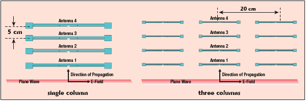
An array of I-tag-like antennas was simulated using the full 3D field-solver CST Microwave Studio (Transient Solver), which uses the finite integration technique. The simulated antenna metal was assumed to be a perfect electric conductor. In the center of the antenna, where the RFID tag IC normally would be attached, a lumped load network was connected with a 1 k? resistor in parallel with a 1.6 pF capacitor. The simulated antenna geometry is shown in Figure 1. Figure 2 shows the arrangement of antennas for the single- and three-column array cases.
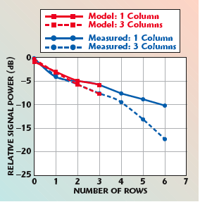
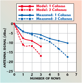
To be able to determine the power delivered to the resistive load, which represents the real load of the tag IC, a voltmeter was connected in parallel with the resistor. The antenna calculation space was terminated with open boundary conditions except for along the symmetry line of the antenna where an electric boundary condition was used. Identifying a symmetry-plane in the set up helped cut the number of calculated mesh cells in half. In this simulation set up, no discrete or waveguide ports were defined. Thus, no S-parameters were calculated. Instead, a plane wave excitation source was used with linear polarization. The E-field vector was parallel to the I-tag antennas with broadside propagation orthogonal to the antennas. The amplitude of the electric field was set to be 1 V/m. The simulated results, using a shunt capacitance of 1.6 pF and a shunt resistance of 1 k? at 910 MHz (insignificantly different from the 915 MHz used in the measurement), are compared to the measured data in Figure 3. Excellent agreement is obtained with the measured results for both a single column and three columns. Note that the model and measurement are of comparable rather than identical quantities: the numerical data are based on the voltage at successive elements of the center column of the array with all elements present, whereas the measured data is taken by adding successive rows to the array with a fixed receiving antenna (see Figure 18 in Part I). The close agreement between theory and experiment suggests that the strong effects of arrays of tag antennas on measured fields are real and expected for a typical array of tag antennas. The numerical results are quite sensitive to the load impedance value. For example, if the assumed capacitance is reduced to 0.8 pF, the effect of the array is considerably magnified (see Figure 4). This sensitivity can be roughly understood by considering the radiating part of the antenna as predominantly capacitive, and treating the shunt central region as an inductor; in this case, the equivalent circuit of the system including IC is roughly a capacitance Cs in series with the shunt combination R, L and C of the simulated geometry. Thus, for fixed parameter values, a series resonance with maximum current flow is expected in the radiating portion (and maximum scattering), and a parallel resonance of Lp and Cp, typically at a slightly higher frequency, with large reactive currents in the shunt portion and minimal current flow in the series (radiating) part. Corresponding to these differing conditions, a differing voltage gain is expected from the impinging electric field to the IC contacts, affecting the ability of the IC to rectify the incoming RF power and turn on. The radar cross-section is proportional to the square of the current flow in the radiating portion of the antenna, so the measured variations in RCS (see Table 2 in Part I) suggest that array effects will vary with tag design and frequency.
Simplified Analytic Model for Tag Arrays
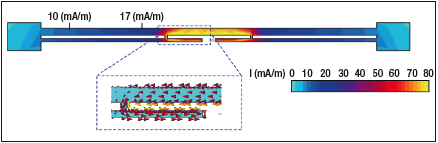
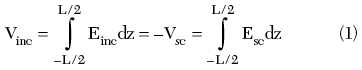
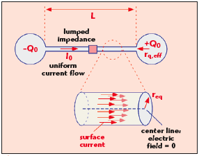
Numerical simulations of the type discussed, in which the detailed current distribution for each antenna element is self-consistently established, require specialized software, and are difficult to scale to large arrays. A considerable amount of work has been done on both numerical and analytic solutions to the problem of array fields for large but finite arrays.2-6 In particular, many treatments assume the validity of the Floquet theorem, which states that the current on all elements of the array is of the same magnitude and varies only in phase from one element to the next. This theorem is valid for an infinite array, but is in serious error for a finite array illuminated near end-fire (that is, in the plane of the array). However, Hill and Cha4 showed that reasonable results can often be obtained by applying Floquet’s theorem individually during the calculation of the current on each individual element of the array, while allowing the current magnitude to vary when different element currents are calculated. This approach is roughly equivalent to assuming that the current magnitude varies slowly along the array so that the local currents on any given element are of similar magnitude and their relative phase dominates the determination of the total field strength. The numerical results also suggest a simplified approach to modeling the antenna currents and charges for typical RFID tag designs. Figure 5 shows the simulated current magnitude for an I-tag antenna with a 1.6 pF shunt load capacitance at 915 MHz. Along the radiating portion of the antenna, the current varies from approximately 17 to 10 mA/m; that is, there is only approximately a 25 percent variation from the average value of approximately 13.5 mA/m. Large gradients in current density, observed in the loading regions at the ends of the antenna, show that charge is stored in these regions. The inset is a close-up of the inductive shunt region, showing that the currents flowing on the two arms of the antenna are opposed and approximately cancel one another, leading to relatively little radiated power from the central region. Guided by these results, a simplified analytic model of element antennas appropriate for many RFID tags is proposed, consisting of a radiating region along which the current is constant, a charge storage region at the ends in which no current flows and a central lumped-element load (see Figure 6). The radiating region is modeled as a cylinder with some equivalent radius req; the end regions provide a capacitive charge storage with an equivalent size rq,eff. The effect of the central lumped impedance is to reduce the value of the peak current flow. (This is a reasonable approximation as long as the impedance is comparable in magnitude to the radiation resistance of the remainder of the antenna; for large central impedances one must account for the change in current distribution along the radiating region.) A further simplification that should be valid for most tag designs within their intended frequency range is obtained by taking into account the fact that in most cases a tag antenna will be designed to provide a conjugate match to the load impedance presented by the IC. As a consequence, the current flow on an isolated antenna can be assumed to be in phase with the incident field. An example of the application of this analytic approach to an end-fire array will be provided. The last element of a linear array with J elements in the plane of propagation, offset from each other by a distance ?y, is considered first. In the particular case of the last element of an end-fire array, the sum of the delay from the source to an earlier element, and from that element to the end is constant, so the contributions from preceding tag antennas can be added in phase in the Hill and Cha approximation. The effect of other elements can be split into a scalar (electric) potential and magnetic potential (mutual inductance). The scalar potential contribution is only significant from the nearest-neighbor antenna when the spacing is small compared to the antenna size. The vector potential contribution decreases approximately as 1/n ?y and thus does not converge as the array grows larger. (The Hill and Cha approximation in this case ignores the phase shift along the array that would actually exist, and so slightly overestimates the contribution of distant antennas.) The boundary condition is the requirement that the scattered electric field Esc due to the currents on all the antennas is the negative of the incident field Einc at the last antenna, so that the total field within the wire is zero (see Figure 6). In integral form
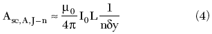
The scattered voltage from the Jth tag antenna (self-voltage) is simply due to the radiation resistance and the series equivalent resistance of the IC
![]()
where
I0 = current along the antenna, presumed constant
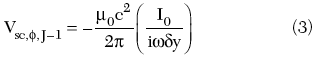
The scalar potential contribution from the next-neighbor antenna (J-1) is approximately due only to the charge localized at the ends of the element. If ?y is small compared to L
The scalar potential contribution from more distant antennas (J-2), etc. will generally be negligible. The magnetic contribution is obtained from the vector potential, in this case along the axis of the antenna (so that only the x component is considered). To a reasonable approximation
Though for small ?y, one should slightly modify the contribution from the nearest antenna
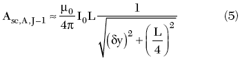
The electric field due to the vector potential is –i?A; this potential is approximately constant along the antenna, so the associated voltage is obtained by multiplying by L. Summing all the contributions
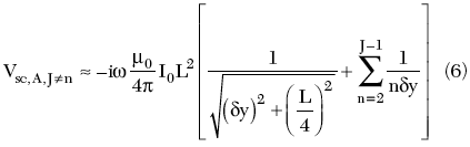
The total scattered voltage, obtained by adding all the contributions above, is set equal to minus the incident voltage
![]()
Since each contribution is proportional to the current on the antenna I0, the resulting current is inversely proportional to the total impedance due to each contribution to the voltage. The power delivered to the end of the array relative to that incident on an isolated antenna in the same location is then
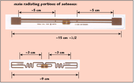
Because of the local Floquet assumption, no iteration is necessary: this model may readily be implemented in a spreadsheet or other general mathematical environment, and the computational time is negligible, even for large arrays. In order to apply the model, the fact that in general, the effective (radiating) length of a tag antenna is not the same as the physical end-to-end length, must be accounted for. Examples are shown in Figure 7 for the I-tag and Squiggle tag; reasonable estimates of the radiating lengths of these antennas are approximately 10 and 6 cm, respectively.

In Figure 8, the relative intensity for varying array sizes is shown, for two different values of the antenna length L, roughly corresponding to the I-tag and Squiggle tag, respectively, predicted from the simple model for a tag array. In all cases, the relative power is measured at the most distant tag (the far end of the array from the transmitting antenna). The model results are shown for a single column with a spacing of 5 cm in the propagation direction. Also shown is the experimental data for this configuration from Figure 19 in Part I. This very simple model provides a semi-quantitative agreement with the measured data, and explains the difference between the two types of tags primarily in terms of the difference in their effective radiating length. The simple analytic model is not nearly as accurate as the full numerical model, but can be scaled to large or complex arrays more readily than the numerical model.
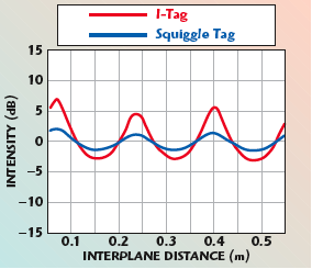
When arrays other than a simple linear end-fire configuration are considered, both the phase offset between the element currents, due to the local Flocquet assumption, and the phase delay due to propagation from each remote element J to the element of interest must be explicitly accounted for. Equations 3 to 6 become slightly more complex, as phase factors must be included, and a full complex number implementation is needed to perform model calculations, but otherwise the model is not significantly altered. An example of a result for a more complex geometry is shown in Figure 9. Here a pair of plane arrays was modeled. Each plane contains a three by nine array of tag antennas, making this problem challenging to implement using a self-consistent numerical approach. The intensity in the center of the rear plane is plotted for parameters representing Squiggle and I-tag antennas. The expected half-wave periodicity can be observed and qualitative agreement with the data in Figures 10 and 12 in Part I is obtained.
In order to use this analytic approach as a systematic and accurate tool for general-purpose modeling of large RFID tag arrays, it will be necessary to establish a detailed correspondence with numerical simulations of various tag designs or measurements, obtained for example from radar cross-section data, so that appropriate parameters can be employed for each given combination of tag design and frequency of operation.
Conclusion
In this article, reasonable estimates of the load presented to the tag antenna by the integrated circuit have been shown permitting to reproduce the measured behavior of a simple array of single-dipole tags and providing theoretical confirmation that tags create substantial attenuation of incident signals in geometries reasonably representative of realistic commercial applications. Array effects are very sensitive to assumptions about the central IC impedance, and thus would be expected to vary with frequency and tag design. It is also shown that a simplified analytic theory for this interaction shows promise for providing a practical modeling tool, which can be implemented readily using general-purpose software tools and can deal with arrays much larger than those that are convenient to model using 3D simulation software.
Acknowledgments
The authors would like to thank Jim Buckner, Kathy Radke, Titus Wandinger, Jose Hernandez, Don MacLean, Dan Kurtz and Walter Strifler for their assistance with this work.
References
1. D.M. Dobkin and S.M. Weigand, “UHF RFID and Tag Antenna Scattering, Part I: Experimental Results,” Microwave Journal®, Vol. 49, No. 5, May 2006, pp. 170–190.
2. http://www.chemsoc.org/exemplarchem/entries/ 2003/bristol_cook/latticetypes.htm and http:// www.matter.org.uk/diffraction/geometry/3D_ reciprocal_lattices.htm.
3. B. Munk, R. Kouyoumjian and L. Peters, “Reflection Properties of Periodic Surfaces of Loaded Dipoles,” IEEE Transactions on Antennas and Propagation, Vol. 19, No. 5, September 1971, p. 612.
4. D. Hill and C. Cha, “Quasi-infinite Array Scattering Technique,” 1987 IEEE Antennas and Propagation Symposium Digest, paper AP06-2, p. 264.
5. J. Jin and J. Volakis, “Electromagnetic Scattering by a Perfectly Conducting Patch Array on a Dielectric Slab,” IEEE Transactions on Antennas and Propagation, Vol. 38, No. 4, 1990, p. 556.
6. B. Tomasic and A. Hessel, “Analysis of Finite Arrays – A New Approach,” IEEE Transactions on Antennas and Propagation, Vol. 47, No. 3, 1999, p. 555.