
In "The Innovator's Dilemma" (1997), Clayton Christensen, Professor of Business Administration at the Harvard Business School, coined the term "disruptive technology" to describe innovation that changes the fundamentals of an existing market and related value network through displacement of an entrenched technology. Although the phrase connotes an abrupt transition, the innovation itself often takes years to develop and be adopted.
Christensen described a process by which a product or service initially took root in simple applications at the bottom of a market and then relentlessly moved "up market," eventually displacing established competitors. In contrast, he defined "sustaining innovation" as a continuous evolution of an existing technology by the established market leaders to remain competitive. This type of innovation does not necessarily create new markets, but does have the ability to transform the market with better products and services. Yet it is the disruptive technology that drastically lowers prices, enables new functionality or alters product efficiency, desirability or competitive advantage to the extent that the market is changed forever.
Established companies in technology-driven markets recognize the need for continual technology development; yet many remain vulnerable to unforeseen market innovations. Unfortunately, in today's current business climate many companies are unwilling to redirect their scarce resources away from immediately profitable ventures for fear that they cannot afford to invest their R&D beyond sustaining innovations, such as those needed to compete against current competition. And yet, market leaders need to be on the alert for innovations occurring elsewhere in their industry, lest a game changing technology transforms the market and leaves them behind.
In "The HP Phenomenon" (2009), Charles House and Raymond Price tell the story of how Hewlett-Packard innovated and transformed itself six times. Continually prevailing over each challenge, the company came across along the way. Early on, David Packard observed that "change and conflict are the only real constants." As a result, HP developed internal philosophies, practices and organizational principles that led to a sequence of innovations and transformations, made possible through the company's customer-centered, contribution-driven, and growth-focused approach.
The "HP Way," with its emphasis on bottom-up innovation and the flexibility to see results brought to the marketplace, is a classic example of what is required to develop disruptive technologies. Perhaps HP's most drastic game changer took place in the 1960s when the company was the start-up risk taker. During that time, test equipment utilizing HP's semiconductor technology was able to displace the tube-based test equipment manufactured by then-market leader General Radio (GenRad). From there, test equipment became highly automated through computer control and the market never looked back.
According to Christensen, a firm's existing value network(s) often places insufficient value on pursuing disruptive innovations. In contrast, start-up companies have a different set of value networks and operating costs, which allow them to take more risks and follow an alternative path of innovation, one that is not tied to an established method.
This risk taking approach to R&D was glorified in the "Think Different" advertising campaign from Apple Computer, coincidently in the same year "The Innovator's Dilemma" was published.
The Crazy Ones – Apple’s “Think Different” Ad campaign
"Here's to the crazy ones. The misfits. The rebels. The troublemakers. The round pegs in the square holes.
The ones who see things differently. They're not fond of rules. And they have no respect for the status quo. You can quote them, disagree with them, glorify or vilify them.
About the only thing you can't do is ignore them. Because they change things. They invent. They imagine. They heal. They explore. They create. They inspire. They push the human race forward.
Maybe they have to be crazy.
How else can you stare at an empty canvas and see a work of art? Or sit in silence and hear a song that's never been written? Or gaze at a red planet and see a laboratory on wheels?
We make tools for these kinds of people.
While some see them as the crazy ones, we see genius. Because the people who are crazy enough to think they can change the world, are the ones who do."
More than a decade later, Apple's iPhone played a significant role in establishing the Smartphone category and transforming the slumping mobile phone market (22 percent decline in US sales in 2008) into one of high growth and profitability. In this case, the disruptive technology was the phone itself - with its ergonomic and user-friendly look and feel, not to mention the cool factor. But the microwave technologists designing components for these handsets also needed to innovate to enable the multi-mode, multi-band radios inside these products.
For microwave companies building the passive and control components found in RF/mW front-ends, mobile devices and infrastructure, test equipment or Radar/EW systems, sustaining innovation is about improving insertion loss, filter selectivity, switching speeds, reliability, etc. in order to outperform their competitors. Additionally, the market demands manufacturers build smaller passive components with more integrated functionality. Miniaturization leads to greater circuit density, which in turn leads to an increase in parasitics and poorer electrical performance at high frequencies. To overcome this degradation, researchers are focusing their attention on new materials and novel structures. These research efforts target both printed circuit boards and semiconductors.
If Christensen is right, one could expect to find disruptive innovation coming from little known start-ups with a tolerance for risk or from radical larger firms, such as Apple and early HP – companies that have institutionalized a process for breaking the rules. Still, even Apple and HP innovations were initially linked to research from places such as Stanford, UC Berkeley and Xerox PARC.
Given the "bottom up" nature of disruptive technologies, anyone scanning the horizon for such developments needs to keep a close eye on published research and watch for its evolution toward productization. The following technologies are in different states of making this transformation. Whether any of them has the potential to disrupt the market remains to be seen.

Figure 1 Examples of SIW construction showing metal (top/bottom) and dielectric layers along with via side walls.
Substrate Integrated Waveguides for Greater Power Handling and Lower Loss
Substrate integrated waveguide (SIW) structures also known as laminated waveguide or post-wall waveguide have received some attention over the past several years. The construction offers easy fabrication while sharing comparable electrical and mechanical performances with conventional rectangular waveguide. This new family of transmission line and distributed planar waveguide component is formed by a dielectric substrate and densely arrayed metalized posts or via-holes that form side-walls connecting upper and lower metal plates, which sandwich the substrate material. The metal layers along with the array of metalized via-holes define the waveguide walls as shown in Figure 1.
Developments in SIW technology target both multi-layer PCB and CMOS substrates and can be easily fabricated with through-hole techniques for low cost and mass-production. The post-wall waveguide is known to have similar guided wave and mode characteristics to conventional rectangular waveguide with equivalent guided wavelength. The resulting power handling capability and low loss performance of the SIW are much better than conventional transmission planar lines.
In the February Microwave Journal cover story, R. Holtzman of Elisra Electronic Systems (Israel) wrote that "one current area of research is substrate integrated waveguide (SIW) components. Using this technique, some of the alumina filters may be replaced by SIW filters." In a Microwave Journal article appearing last December, Y. Yun employed a periodically arrayed grounded-strip structure (PAGS) on silicon substrate to create an ultra-wideband, multi-section transformer using a Chebyshev polynomials design technique. At 0.026 m2 on a silicon substrate, the resulting transformer was more than 90 percent smaller than the one fabricated using conventional coplanar waveguide and showed good RF performance over an ultra broadband from 8 to 49.5 GHz.1
High precision PCB manufacturing techniques including LTCC should support passive component design using SIW structures to extend up to the 100 GHz range while advanced micro-fabrication techniques, such as photo-imaging, micromachining, CMOS process, and others, have the potential to push design of substrate integrated structures up to the hundreds GHz and THz range.2

Figure 2 Metamaterial formed by an array of complementary split ring resonators.
Metamaterials: Materials Unbounded or Weird Science
Metamaterials are synthetic materials constructed from periodically arranged, resonant conductive sub-wavelength elements with specific inductive and capacitive characteristics (see Figure 2). These structures manipulate the flow of electromagnetic energy in ways that cannot be achieved with naturally occurring substances. At microwave frequencies, they have demonstrated great promise in high performance beam steerers, modulators, bandpass filters, lenses, couplers and antenna systems. Planar metamaterials and metamaterial resonators are easily incorporated into microwave circuits and support passive component size reduction and the high integration densities required by mass-market wireless communications.
Metamaterials' greatest potential lies in its ability to create a structure with a negative refractive index. Most materials, whether they are a conductor or insulator, have positive permittivity and permeability values, resulting in an ordinary index of refraction. Metamaterials, however, are able to exhibit a state where both permittivity and permeability are negative, resulting in an extraordinary index of negative refraction. For plane waves propagating in electromagnetic metamaterials, the electric field, magnetic field and wave vector follow a left-hand rule.
In 2000, microwave frequency metamaterials from horizontal stacking of periodically placed split-ring resonators and thin wire structures was first demonstrated. In 2002, a method was developed to realize negative index metamaterials using artificial lumped-element loaded transmission lines in microstrip technology.3 By 2006, metamaterials advanced the state of stealth technology when the first real invisibility cloak at microwave frequencies was realized.4
This past May, G. Jang and S. Kahng presented a metamaterial bandpass filter in Microwave Journal. In the design, an intermediate gap was used to provide capacitive coupling between neighboring zero-order resonators formed by half circular, mushroom-shaped cells. Along with an improvement in the stopband performance, a size reduction of more than half that of a conventional filter (based upon half-wavelength resonators) was achieved.
Nanotechnology: The Path to Higher Circuit Densities
Nanotechnology is expected to be an enabling technology for many of the new electronic devices and circuits, including those for communication, sensors, imaging and advanced medical applications. Nanoelectronic materials and devices, such as carbon nanotubes, graphene, spin-flip electronic devices and superconducting quantum interference devices, are expected to offer higher integration densities and substantially improved microwave properties. The field of nanotechnology is quite broad.
For instance, with its high carrier mobility and saturation velocity, attention is being focused on the development of graphene-based transistors for RF applications. Synthesis of large-scale graphene sheets of high quality and low cost has been demonstrated using chemical vapor deposition (CVD). Using this manufacturing technology, Scientists at IBM have managed to create a graphene transistor that operates at 155 GHz. The carbon-based graphene transistor was developed together with DARPA to be used in radio frequency technology and reach extreme clock frequencies through its molecular characteristics where the hexagonal pattern makes it possible for electrons to move at incredible speeds.
At the University of Southern Florida, magneto-dielectric polymer nanocomposites are being investigated as a new class of functional materials for use in RF and microwave applications. Magnetite (FE3O4) nanoparticles homogeneously dispersed in a polymer matrix were shown to exhibit low loss at microwave frequencies. The mono-dispersion of the magnetic nanoparticles, with sub-10 nm diameters and tight size distribution, enhanced the microwave properties of the engineered composite material by increasing the relative permeability and relative permittivity. Moreover, complex permeability and permittivity of the nanocomposite material can be tuned by an externally applied DC magnetic field.
High Permeability Ferromagnetic Thin-films to Suppress Skin Effect in On-chip Conductors
At the EuMIC conference, researchers from Japan and Germany presented an overview of RF high permeability ferromagnetic thin films applied to a new ferromagnetic/conductive multi-layer to suppress skin effect in RF on-chip conductors. The combined multi-layer structure has certain properties that are attractive for designing inductive passive components.
At sufficiently high frequencies, the negative permeability of the ferromagnetic films effectively compensates the positive permeability of the nonmagnetic metal layers, leading to an overall suppression of the skin effect. Addressing the increased resistance due to skin effects, researchers believe the multi-layered structure of metal/magnetic thin film will improve the performance of any on-chip conductor, including transmission lines, integrated inductors and antennas in order to realize high-Q and energy-saving systems. Available in various forms, including sputter-deposited metallic alloy, traditional oxides and nano-composites, application trials are ongoing for CMOS integrated inductors, one-chip DC-DC converters and on-chip noise suppression for LTE-era RFIC receivers.
Designing High Q Passives in Liquid Crystal Polymers
Liquid Crystal Polymer (LCP) is a fairly new thermoplastic organic material that offers both low loss and dielectric stability (2.9 at 5.8 GHz) from DC to 110 GHz. LCP has a permittivity value that is particularly well suited for antenna systems because the material naturally prohibits the excitation of surface waves. LCP is also conformal (in thin film form, it is as flexible as paper), so it can be rolled into a cylindrical shape, packed into a rocket payload and launched into space or deployed as an antenna array on the battlefield. Multi-layer LCP devices can be made with a low melting temperature, which gives it a key advantage over other packaging materials. When the footprint size must be minimized, a multi-layer LCP can be used as a combination substrate and packaging material, making it a useful medium for System-on-package and embedded designs.5
LCP is excellent material for designing high Q spiral inductors with quality factors as high as 90 at X-Band for inductance values ranging from 2 to 5 nH. Presentations on high-Q, miniaturized LCP-based passive components and filter design for SoP applications and high-Q multi-layer LCP were presented at this year's European Microwave Week.
In addition, research at UC Davis has recently focused on the development of sealing techniques of LCP onto LCP and LCP onto semiconductor materials to form near hermetic cavities for housing MEMS and MMICs. Using the newly developed sealing techniques, LCP wafer-level packages, surface-mount packages and multi-chip modules to 40 GHz have been realized.
These surface-mount packages were designed with novel feed-through interconnects that achieved a measured insertion loss of ~0.2 to 0.4 dB up to 40 GHz and included embedded filters. Reliability evaluation of the LCP packages included environmental testing at 1000 hours of 85°C and 85 percent humidity as well as temperature cycling and thermal shock testing.6
Antenna Tuning with Adaptive Impedance RF MEMS Modules
Disruption is all well and good when a company is creating a new smartphone category, but Apple had a problem on its hands when its iPhone's antenna reception experienced disruption in the hands of its customers. The output power and radiation efficiency of a mobile phone with a compact narrow-band antenna can be greatly degraded by large mismatches resulting from the user's hand position. Phone manufacturers study the impact using over-the-air testing with the actual phone placed in various positions against hand and head models. Testing all possible hand/head positions is not practical, so over-the-air testing is limited in its ability to detect potential failures. Since multi-mode, multiband phones with densely packed radios and future MIMO antennas will only make next generation designs even more problematic, antennas need to be less sensitive to their environment.
Microwave Journal Technical Editor Pat Hindle discussed recent work with adaptive antenna tuners in "MEMS Tuner Modules Could Solve Handset Reception Problems" (January 2011). These modules dynamically change antenna impedance using a feedback controller so it is always tuned for maximum efficiency. In these modules, a detector measures the transmitted RF signal and an algorithm derives the mismatch information from the phase of the matched input impedance and calculates any necessary changes for the adaptive matching circuit.

Figure 3 A single capacitive RF-MEMS switch with quality factor of 250 at 1 GHz.
A simple series-connected LC matching network compensates the complex component in the antenna impedance variations. A DC-DC controller forces the change in the impedance matching by varying the voltages applied to a varactor in the LC network. This process is repeated until the desired impedance has been reached. TDK-EPC and WiSpry are two companies developing this technology using tunable RF MEMS devices to switch the loading circuit between different valued capacitors in an array.
The module from TDK-EPC uses a binary weighted 5 bit RF MEMS array of electro-statically variable capacitive RF MEMS switches is shown in Figure 3. A high voltage driver generates the MEMS bias voltages. It supports all common frequency bands from 824 to 2170 MHz in a module size of 5 × 5 × 1 mm. RF MEMS offer several distinct advantages over competing varactor technologies, especially linearity and power stability. A single capacitive RF MEMS switch has a Q factor of up to 250 at 1 GHz – three to five times greater than competing technologies – as well as a large tuning range of 10:1.
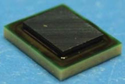
Figure 4 WiSpry's fully integrated tunable impedance matching (TIM) solution (3.5 × 4.0 mm).
Earlier this year, WiSpry announced a partnership with IBM to develop single-chip tunable RF front-ends for mobile handsets, which the company has begun marketing to tier-one original equipment manufacturers. WiSpry's tunable RF MEMS technology, shown in Figure 4, also uses arrays of capacitive devices that can provide more than 3 dB of link resiliency. WiSpry reports similar results as TDK-EPC, including a broadband tuning range of 10:1, +3 to +6 dB of transducer gain and overall efficiency gains of 30 percent or more, depending on the implementation within the handset. WiSpry's standard RF CMOS manufacturing process through the IBM foundry supports integration of RF MEMS devices on active CMOS, setting the stage for future tunable SoCs.
MOSFET Switched Capacitor Impedance Tuning
The downside of tunable impedance networks based on voltage variable capacitors and MEMs switched capacitor banks is that both of these options require 30 to 40 V for operation, which is difficult to produce in a handset. Peregrine Semiconductor is now offering an alternative solution based on MOSFET switched capacitors that permit higher frequency operation, faster switching and higher Q. The company's DuNE technology has yielded a digitally tunable capacitor (DTC) chip that contains five capacitors switched by MOSFETs operating from a serial input bus with a 5-bit code providing 32 possible capacitor values.

Figure 5 View of chip (a) component schematic (b) and packaged Digitally Tunable Capacitors from Peregrine Semiconductor (c).
Making a big debut at this year's MTT-S IMS, Peregrine's DuNE chips offer capacitor values ranging from 0.5 to 10 pF with typical tuning ratios of 3:1 to 6:1, or 10:1 in some cases. Typical switching speed is less than 5 µs. Capacitor Qs greater than 100 are possible. The frequency range is up to 3 GHz, and power handling is up to 40 dBm. The chip operates with a supply voltage of 2.4 to 3 V with current consumption in the 20 to 100 µA range (see Figure 5).
One or more of the devices can be used in an L, T, or π network for matching purposes. The chip can be used in an open-loop fashion with input control from a lookup table or in a closed-loop adaptive tuning network. The closed-loop system uses a directional coupler to sense forward and reflective power. A tuning algorithm is implemented to provide automatic adjustment to bring the VSWR to its lowest possible value. Among the potential applications, Peregrine is promoting the technology for use in mobile TV receivers that must operate over wide frequency ranges. For example, the European DVB-H and Japanese ISDB-T mobile TV systems commonly operate in the 470 to 862 MHz range, creating a massive detuning problem with channel selection.
Switching High Power RF Application with GaN
PIN diodes and GaAs FETs are two widely used technologies in RF switching applications. While FETs offer low insertion loss and high switching speed with minimal DC-bias power requirements, the short source-drain separation required for operating at microwave frequencies leads to the low breakdown voltages, which, in turn, limits their power-handling capability, typically in the range of a few watts. While switches based on PIN diodes have a much higher power handling capability, they consume more DC power and typically require a larger circuit footprint area to incorporate the passive components and multiple diodes that make up their non-integrated design.
GaN switches on the other hand, offer high electric field strength for significantly improved power handling capability along with the size and cost benefits that come with integration into standard MMIC architectures. A couple of GaN suppliers have started to release switch products to the market. TriQuint has developed three broadband GaN on SiC MMIC switches to cover frequency ranges of DC to 6, DC to 12 and DC to 18 GHz. These devices have maximum insertion loss of 0.7, 1.0 and less than 1.5 dB, and demonstrate 40, 20 and 10 W RF power handling, respectively, for 6, 12 and 18 GHz designs. Switching speeds are below 25 ns and the isolation is greater than 30 or 35 dB depending on the device (for more information, see TriQuint's product feature article in this issue, page 132).
TriQuint's GaN process yields a breakdown voltage of 70 V DC compared to about 13 V DC for GaAs and can handle current of more than 1 A/mm of device area versus 650 mA/mm for GaAs. The high thermal conductivity of the insulating SiC substrate reduces leakage caused by high RF voltage swing while also improving heat transfer to the back of the device, which is useful in radar, EW and high power communication systems.

Figure 6 SPDT GaN switch from Cree.
At this year's Compound Semiconductor Manufacturing Conference (CS Mantech), Cree presented results for a 25 W, 0.1 to 3 GHz SPDT GaN MMIC switch featuring less than 0.7 dB insertion loss, 15 ns switching speed, over 30 dB isolation and a TOI over 60 dBm, see Figure 6. And at EuMW, researchers from Fujitsu in collaboration with the Japan Ministry of Defense, presented a 200 W+ high isolation GaN switch for L-Band Radar, indicating that GaN switches are well poised for adoption into numerous applications calling for high power switches with lower current consumption.
Multi-mode RF Filters Save Space
High selectivity, group delay flatness, power handling, insertion loss, weight and volume constraints are among the stringent requirements for today's microwave filter. As a result, many technologies and physical configurations have been introduced to satisfy various performance criteria over a range of applications. New filter configurations, such as single and dual-mode filters with elliptic function responses, have been developed. Combined with new high dielectric constant materials with a high quality factor and low temperature coefficient, these filters have the advantages of low loss, smaller size and superior temperature stability.
With the deployment of micro base stations, including remote radio head (RRH) systems, and the overlay of multiple frequency bands for multiple standards on a single cellular site, the space available for the RF hardware is decreasing. RF filters typically occupy a significant fraction of the base station volume, so base station manufacturers are looking for filter technologies that offer size and cost reduction, while still meeting the stringent base station RF specifications of insertion loss, rejection and power handling.
One such example is the "Black Hole Filter (BHF)" from KMW, which claims to be the first commercialized use of "Triple-Mode" technology, providing high stopband attenuation with low passband insertion loss in a relatively small package. The company's innovative approach to "Triple-Mode" technology enables three distinctive resonances with only one resonant cavity, utilizing a dielectric resonator with high Q value inside the single pocket. Compared to conventional dielectric resonator filters, the triple mode "Black Hole Filter" offers very low insertion loss and high attenuation with a significant size reduction. Inside the pocket, waves can travel without bending and distortion, achieving the highest possible Q and steepest band-edge skirts seen in a single-pocket filter.
Whereas conventional single-mode filters may provide only a single resonance mode in the single pocket, the triple-mode filter generates three distinctive resonances using the same TE01δ mode as the single-mode filter. It also enables two additional TE01δ modes allowing the single cavity to function as three cavities, which improves the performance and lowers the manufacturing cost. The single-mode filter with eight resonators can be replaced by the triple-mode filter comprised of only two resonators while achieving the same performance, occupying less than a third of the size of the conventional cavity filter.
Very-High-Q Solenoid RF Inductors Offer Better Performance on a Variety of Substrates
Inductors and resonators are essential passive components used in the design of most RF circuits, especially oscillators and filters. As such, they have a great impact on the performance and physical size of these circuits. Distributed components require considerable real-estate and, like planar spiral inductors, they may limit circuit performance with a low quality factor. A number of research efforts have focused on re-defining the structure and shape of the RF inductor using via interconnects to synthesize solenoids that offer high Q and can be manufactured on many different substrates.

Figure 7 HFSS model of high Q resonator constructed with planar solenoid inductor with embedded capacitor.
At IMS in Baltimore, researchers from École de Technologie Supérieure in Montréal and Robert Aigner, Director of R&D Acoustic Technologies at TriQuint, presented their work on very-high Q solenoid RF inductors. Targeting SiP LTCC integration, this team produced a compact high-Q three-dimensional inductor topology that achieved a quality factor of 75 and high self-resonance frequency (SRF 4.5 GHz) with inductance-values ranging from 2 to 7 nH at 2 GHz. In the same workshop, a team from University of Alabama in Huntsville presented a high Q tuned resonator based on a two-turn solenoid and embedded capacitor fabricated on RT/Duroid 5880, shown in Figure 7. Measured results showed a quality factor over 300 at 12.25 GHz.
These structures are not restricted to LTCC or multi-layer PCBs. In 2001, Georgia Institute of Technology researchers first reported a fabrication process for high Q solenoid inductors on top of 0.24 μm CMOS technology using surface micro-machined, epoxy-embedded electroplated structures. The six-turn inductor yielded a peak Q-factor of 20.5 at 4.5 GHz and an inductance of 2.6 nH.7 By 2007, a low temperature, two step copper-plating process fully compatible with CMOS technology was used to fabricate solenoid inductors with Q-factors as high as 87 at 14.5 GHz and 35 at 6.4 GHz.8
The increased number of metal layers available in today's CMOS processes will support the development of compact, high quality on-chip vertical solenoid inductors that will continuously reduce the inductor area while increasing the Q and self-resonant frequency (SRF). At this year's RFIC conference at IMS, researchers from Renesas Electronics reported very small on-chip vertically coiled solenoid inductors (V-solenoid) with measured self-resonance frequencies higher than 40 GHz using 90 nm CMOS multilevel interconnect technology.
Are any of these 10 technologies the next big thing for drastically enhancing the performance of passive and control components? Some technologies tend to linger as a perennial favorite of researchers, never quite making it outside the R&D lab. Others slowly work their way into the next generation of products. Modest innovation will only buy so much time in the effort to stay ahead of competition. Eventually, new technologies will disrupt the status quo. Want to really get ahead of the pack? Think different, go crazy.
In Memory of Steve Jobs, 1955-2011
References
- www.mwjournal.com/Article/Miniaturized_Multi_section_Transformer_Si_RFIC_Low_Impedance_Transformation_UWB/AR_10032/
- http://cassnewsletter.org/Volume3-Issue2/Technology_News.html
- G.V. Eleftheriades, A.K. Iyer and P.C. Kremer (2002). "Planar Negative Refractive Index Media Using Periodically L-C Loaded Transmission Lines." IEEE Transactions on Microwave Theory and Techniques, 50(12): 2702-2712.
- www.cmth.ph.ic.ac.uk/photonics/Newphotonics/pdf/CloakPap100406.pdf
- Nick Kingsley, "Liquid Crystal Polymer: Enabling Next Generation Conformal and Multilayer Electronics", Microwave Journal, May 2008, pp. 188-200.
- www.mtt.org/dmls.html
- Y. Yoon, E. Chen, M. Allen and J. Laskar, "Embedded Solenoid Inductors for RF CMOS Power Amplifiers," Proceedings of the 11th International Conference on Solid-State Sensors and Actuators, TRANSDUCERS'01/EUROSENSORS XV, pp. 1114-1117, Munich, Germany, June 2001.
- I. Zine-El-Abidine and M. Okoniewski, "CMOS-Compatible Micromachined Toroid and Solenoid Inductors With High Q-Factors," IEEE Electron Device Letters, pp. 226-228.