Monopole antennas are used in mobile communications. A monopole antenna is a very simple and efficient radiating element.1 The simple whip and monopole antenna are attractive for use in mobile handsets and repeater applications because of their omni-directional characteristics, simple structure and the inherent 2:1 size reduction over equivalent dipole designs.2 However, these antennas suffer from a limited bandwidth and distorted radiation characteristics. In the coming generation of mobile communications, multimedia services will be provided by a mobile handset, which must therefore be equipped with a broadband antenna. The use of a single wideband antenna that covers a wide range of frequencies is very desirable for spectrum monitoring. It is well known that the smaller the size of the antenna, the lower the antenna efficiency and the narrower the bandwidth (a few percent).3 A broadband sleeve monopole with an operational bandwidth of approximately 24 percent was investigated.4 A bandwidth enhancement (36 percent) for a monopole antenna, using a parasitic normal-mode helix, was reported.5 A planar monopole antenna with an operational bandwidth of 44 percent was described,6 and a top-loaded monopole antenna was also reported.7 This antenna had a small size, but its operational frequency bandwidth was very narrow (a few percent).
In this article, a low profile, wideband, top-loaded monopole antenna with four small posts is described. It offers a low radiation resistance within the usable frequency band. The four posts also lead to better omni-directional patterns and higher gain than the conventional top-loaded monopole structures. The top loading also leads to a reduced antenna height (small antenna size). The impedance bandwidth for a VSWR less than 2:1 is adequate for DCS, PCS, IMT-2000 and WLL.
Antenna Structure and Experimental Results

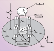
The structure of the proposed low profile, wideband, top-loaded monopole antenna with a ring-shaped plate is shown in Figure 1. It consists of the post-type monopole, a dielectric-layer, a top-load, four posts placed at 90° from each other, a circular ground plane and a 50 ?, N-type connector. Rm is the radius of the monopole, hm is the height of the monopole, htl is the height of the top-loading piece, hpp is the height of the posts, Rtl and Rpp are the radii of the top-loading piece and the posts, respectively, and Rg is the radius of the circular ground plane (reflector). The 50 ?, N-type connector is located at the center of the z-axis to feed the proposed antenna. A rectangular dielectric piece, 7 × 7 × 3 mm, is placed at the bottom of the monopole. The top loading is used to reduce the height of the monopole element and to enhance the omni-directional patterns. The additional four posts also lead to a wider bandwidth and higher gain than for the conventional top-loaded monopole structures. The top loading reduces the high angle radiation, which leads to a decrease in multi-path fading and increases the service area.8 A photograph of the fabricated antenna is shown in Figure 2.

The characteristics of the antenna depend highly on the design parameters:
Rm = the radius of the monopole element.
Hm = the height of the monopole element.
Htl = the height of the top-loading piece.
Hpp = the height of the posts.
Rtl = the radius of the top-loading piece.

Rpp = the radius of the posts.
Rg = the radius of the ground plane (reflector).
Gmp = the gap between the monopole and the posts.
Gpp = the gap between posts.
The fabricated antenna dimensions are: Rtl = 5.5 mm, htl = 2.8 mm, Rm = 3 mm, hm = 28 mm, Rpp = 3 mm, hpp = 17 mm, Rg = 55 mm, Gmp = 15 mm and Gpp = 22 mm. The post-type monopole is used to enhance the impedance matching. In this study, the circular ground plane is made of aluminum, 1.0 mm thick, and the post-type monopole is also made of aluminum with a 3 mm radius.

The measured VSWR versus frequency of the proposed antenna is shown in Figure 3. The experimental impedance bandwidth is approximately 1.62 to 2.82 GHz (54.5 percent bandwidth for a center frequency of 2.2 GHz) for a VSWR less than 2:1. The aluminum weight is relatively light and its conductivity is good. This material is not easily affected by rain or sunshine and permits a relatively low fabrication cost.
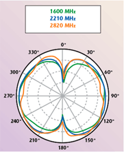
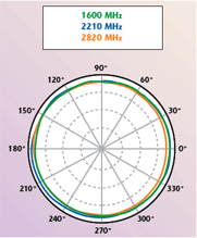
After calibration, using a horn antenna, the radiation patterns in the far field were measured. An investigation of the radiation pattern characteristic of this antenna shows them to be similar to those of a conventional monopole. In Figure 4, the measured y-z plane radiation pattern of the proposed antenna is bi-conical at the center frequency f = 2.2 GHz. The x-z plane radiation pattern is omni-directional without distortions, as illustrated in Figure 5.
Figure 6 shows the measured antenna gain in the x-z plane for operating frequencies across the PCS and IMT-2000 bands. The peak antenna gain is 1.2 dBi for DCS, PCS and IMT-2000 operations, but drops off rapidly past the band edges. This is due to impedance mismatch and pattern degradation, as the back radiation level increases rapidly at these frequencies.
Conclusion

In this article, a low profile, wideband, top-loaded monopole antenna with four small posts is described. A post-shaped monopole is used to enhance the impedance matching, which results in a low radiation resistance within the usable band. Four additional posts also lead to better omni-directional patterns and higher gain characteristics. Additionally, top loading also reduces the height of the antenna (smaller antenna size). A ring-shaped plate also leads to a wider bandwidth and higher gain than the conventional top-loaded monopole structures. The top loading reduces the high angle radiation, which leads to a decrease in the multi-path fading and to an increase in the size of the service area. An experimental bandwidth of 54.5 percent (1.62 to 2.82 GHz) was measured for a VSWR less than 2:1. This antenna provides a wide bandwidth and a high gain characteristic. The proposed antenna can be used in PCS, DCS, IMT-2000 and WLL applications.
References
1. M. Weiner, S. Cruize, C.C. Lee and W. Wilson, Monopole Elements on Circular Ground Plane, Artech House Inc., Norwood, MA, 1987.
2. J. MacLean, H. Foltz and G. Crook, “Broadband, Robust, Low Profile Monopole Incorporating Dielectric Loading and a Distributed Capacitive Feed Mechanism,” 1999 IEEE Antenna and Propagation Symposium Digest, Vol. 3, pp. 1562–1565.

3. K. Fujimoto and J.R. James, Mobile Antenna Systems Handbook, Artech House Inc., Norwood, MA, 1994, pp. 65–70.
4. J.I. Moon, S.O. Park and K.Y. Park, “Broadband Sleeve Monopole Antenna for Dual-band PCS/IMT-2000,” Electronics Letters, Vol. 36, 2000, pp. 1829–1830.
5. Y.W. Chow, E.K. N. Yung and H.T. Hui, “Bandwidth Enhancement of Monopole Antenna by Using a Parasitic Normal-mode Helix,” International Journal of Electronics, Vol. 88, 2001, pp. 557–593.
6. J.A. Evans and M.J. Ammann, “Planar Monopole Design Consideration Based on TLM Estimation of Current Density,” Microwave and Optical Technology Letters, Vol. 36, 2003, pp. 40–42.
7. H. Jiang and H. Arai, “FDTD Analysis of Low Profile Top-loaded Monopole Antenna,” IEICE Transactions on Communications, Vol. E85-B(11), 2002, pp. 2468–2475.
8. C.A. Balanis, Antenna Theory, John Wiley & Sons Inc., Hoboken, NJ, 1997.
