

An antenna measurement facility is typically one of the largest capital investments an antenna manufacturer makes. Therefore, companies commonly specify a test range that seeks to fulfill all requirements within a single chamber. In the resulting facility design, the overall physical dimensions are driven by the largest expected test antenna, typically in the lower frequency bands, while dimensional tolerances are driven by the high frequencies, where antennas tend to be small.
Such tradeoffs invariably lead to a large test facility having to meet tight electrical and mechanical tolerances. In addition to being costly, this type of system can be cumbersome and necessitate significant reconfiguration between high and low frequency operation. It also needs large antenna positioners, requiring operator time, personnel, and machinery to mount and align even small antennas. The compounding time lost on setup will impact range productivity and Return on Investment (ROI). A better approach is multiple test facilities dedicated to certain categories of antennas.
The Microwave Vision Group’s CR-M mini-compact range is a complete, self-contained compact range test system targeting smaller aperture antennas. It provides no loss in accuracy and can be set up by just one person in a matter of minutes. Faster setup translates to improved test efficiency and productivity. CR-M offers a high performance solution for testing antennas up to 50 cm in diameter and in frequencies above 4 GHz. With limited initial investment and high test throughput, it offers antenna manufacturers a high ROI.
CR-M is usable at frequencies up to 110 GHz, and potentially much higher. It is a perfect solution for a wide variety of applications, including small, high gain antenna characterization and millimeter-wave applications. The system’s small size and portability makes it well-suited when space is at a premium, such as production testing or in multi-purpose test and research labs.
Compact Range Technical Background
To characterize the performance of an antenna, we seek to measure its efficiency and radiated energy distribution in space. In most real-use scenarios, a receive antenna is far away from a transmitting antenna, such that the wave front near the receive antenna approaches a “plane wave.” To replicate this in a far-field test range, a guideline for the minimum distance is 2D2/λ, where D is the maximum diameter of the antenna aperture and λ is the wavelength. At this distance, the deviation from a plane is only 1/16th of a wavelength. The far-field distance can grow very rapidly at higher frequencies. For instance, an antenna with a 40 cm diameter at 50 GHz already has a distance of 53 m.
A compact range reflector collimates the wave front of the feeding antenna such that the reflected wave in the test zone (quiet zone) represents a plane wave. In this way, it is possible to directly measure far-field performances in a very compact facility. For example, MVG’s CR-M16 has exterior dimensions that do not exceed 3 m.
System Components and Specifications
As mentioned earlier, the CR-M is a full compact range system contained in a smaller package. It includes an aluminum chamber enclosure lined with absorber, an aluminum-rolled edge reflector, a positioning subsystem complete with AUT and feed positioners and a positioner controller, and an RF subsystem. For ease of use, the system is also available with automatic door (hatch) open/close.
CR-M reflectors are precisely machined from a single piece of aluminum and result in accuracies that allow measurements into the hundreds of GHz. The lower frequency limit of a compact range is restricted by the stray signal level due to reflector edge diffraction. Through continuous improvements in edge design, the latest CR-M systems allow measurements as low as 4 GHz.
Three standard system sizes are available, based on desired quiet zone dimensions from 30 × 30 to 50 × 50 cm.
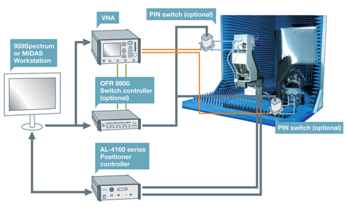
Figure 1 Mini-compact range standard system block diagram.
Typical System Configuration
The CR-M’s basic configuration (shown in Figure 1) allows for single plane patterns to be collected using standard vector network analyzers. The chamber provides a modest level of shielding and allows for easy access to the AUT positioner and compact range feed area. The chamber is mounted on a caster assembly for convenient transportation.
A compact range feed polarization rotator allows the transmit polarization to be changed during a single test or between tests. Linked axis motion of the transmit rotator and optional roll axis allows for automatic acquisition of E and H plane patterns in a single test. An AL-4160 series positioner controller allows for control of up to four axes and simultaneous motion. The use of an OFR 9800 high speed switch controller permits collection of multiple channel data. An optional squint (elevation) axis allows E and H plane patterns through the peak of the beam in case electrical and mechanical bore sight do not coincide. The data acquisition workstation comes equipped with either 959Spectrum or MiDAS software (region-dependent), allowing for versatile and powerful data acquisition and analysis.
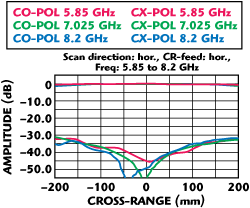
Figure 2 Horizontal quiet zone scan showing co- and cross-polization levels. Amplitude ripple: ±0.3 dB; phase ripple ±0.5°.
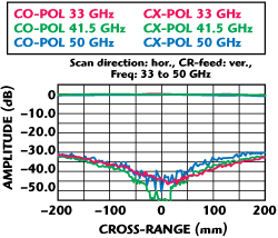
Figure 3 Horizontal quiet zone scan showing co- and cross-polization levels. Amplitude ripple: ±0.07 dB; phase ripple: ± 1°.
Measured System Performances on CR-M16
The quality of the plane wave generated by the compact range is the key measure of range performance. It is measured by translating a probe antenna within the quiet zone while recording the received signal. Figures 2 and 3 show examples of test data for a recently delivered system.
Results show the phase deviation at 50 GHz to be less than 3 electrical degrees peak-to-peak (1/120th wavelength), so that not until 750 GHz, well above maximum frequency spec, is the total phase variation in the order of 1/16th wavelength obtained. In a “real” far-field facility operating at this frequency, a 40 cm antenna would need a minimum distance of 800 m.
Summary
Users of MVG’s CR-M systems rapidly realize its benefits and enjoy increased productivity. These systems enable the full characterization of dozens of antennas in a single day. Brandon Hunter, Functional Test Manager at L-3 Communication Systems – West, has said of his CR-M, “The Mini-Compact Range has very quickly become an indispensible part of our ability to keep up with our antenna test needs. They (the technicians) already wonder how they ever got along without it.”
Microwave Vision Group
ORBIT/FR, Horsham, PA
(215) 674-5100
www.microwavevision.com