
Fundamentally, cognitive radar refers to the next generation of adaptive radar that has unprecedented transmit-receive adaptivity and diversity, along with “intelligent” high performance embedded computing; in other words, the radar adapts “intelligently” to its environment based on a plurality of potential information sources.1,2 Consider the definition of cognition afforded by the National Institute of Mental Health:3 “Cognition: Conscious mental activity that informs a person about his or her environment. Cognitive actions include perceiving, thinking, reasoning, judging, problem solving and remembering.”

A mapping of these attributes to a cognitive radar architecture is provided in Table 1. (Note: Do not worry if some of these terms are unfamiliar at the moment—read on!) While some of these attributes are present to some degree in conventional radars—adaptive receiver processing, for example (that is adaptive beamforming, adaptive constant false alarm rate (CFAR), thresholding, etc.)4—they are generally highly constrained and specialized due to the demands of real-time signal throughput and available real-time knowledge sources. Cognitive radar architectures offer the potential of dramatically improving the sophistication of adaptivity (both transmit and receive), through the exploitation of a plurality of knowledge sources (both endogenous (internal) and/or exogenous (external)).2

What is driving the need for cognitive radar? Table 2 highlights just some of the challenges facing modern radars that, in principle, can be alleviated by incorporating cognitive radar concepts: Everything from complex, highly chaotic clutter (both natural and manmade), to advanced electronic attack and spectrum crowding.5 Conventional adaptive radars rely exclusively on sample statistics derived from the received data stream and, consequently, can suffer a loss in performance in highly non-stationary interference environments.6 Cognitive radars aim to provide much more sophisticated methods of adaptation using high fidelity contextual (such as environmental) knowledge sources, as well as organic sensor data.2
Before delving into the details of a cognitive radar, let us first consider how a modern conventional radar operates. While fairly generic, we will focus on architectures associated with modern airborne moving target indicator (MTI) (either air-to-air (AMTI) or air-to-ground (GMTI)),4 which often have the most demanding requirements due to complex (and potentially hostile) operating environments.7
Referring to Figure 1, there are four high level salient functional elements of the generic MTI radar architecture:

Figure 1 Example of a conventional (non-cognitve) radar.5
- Radar Scheduler
- Transmit Chain
- Receive Chain
- Data Product Generation
Note that virtually all true “channel adaptivity” (adaptivity to the ever changing target plus interference environment) occurs only in the receive chain—and a highly constrained adaptivity at that, as previously described. Conventional radar transmit chains generally employ non-adaptive (and often “pre-canned”) waveforms, which at best employ only mode flexibility (PRF, bandwidth, etc.). By far the most ubiquitous waveforms are the family of linear frequency modulation (LFM), which enjoy a number of properties amenable to cost-effective hardware implementation and robust and reliable implementation (a discussion on “stretch” and other LFM properties, such as Doppler mismatch tolerance has been described by Richards).4 Note that this lack of transmit waveform diversity essentially precludes “feedback” from the receive chain to the transmitter. As has been emphasized by Haykin,1 this feedback is an essential element of any cognitive sensor system. Thus, at best, adaptivity of the radar scheduler is reduced to adaptive “mode” selection (that is high versus low PRF, etc.).

Figure 2 Example of a knowledge-aided (KA), fully adaptive cognitive radar architecture.5
Now contrast the conventional radar architecture with that of a cognitive radar, an example of which is depicted in Figure 2. Note the addition of a number of additional subsystems and additional adaptivity:
- Adaptive Radar Scheduler
- Adaptive Transmit Chain
- Adaptive Receive Chain
- Environmental Dynamic Database (EDDB)
- Knowledge-Aided (KA) Coprocessor
- Data Product Generation
The inclusion of a knowledge-aided (KA) coprocessor and environmental dynamic database (EDDB) allow for the inclusion of new information sources to aid in overall adaptivity. Note the inclusion of feedback to the transmitter, which has been identified by Haykin as an essential element of any cognitive sensor system.1
The two main new elements are adaptivity on transmit and the introduction of knowledge-aided (KA) processing. Both of these subsystems are discussed in greater detail later in this article. The role of the KA coprocessor and the EDDB is fundamentally to provide an accurate estimate of the dynamic radar channel.
For example, in the case of complex clutter, not only is the receive radar data stream available for sensing the clutter environment, but a multitude of knowledge sources are now available in the EDDB and accessible in real-time through an HPEC architecture pioneered by the Defense Advanced Research Projects Agency’s (DARPA) KASSPER project5 (see section titled “Knowledge-Aided Processing for Enhanced Real-Time Adaptivity”).
As the name implies, the new adaptive transmit chain allows for the channel adaptivity of all transmit degrees-of-freedom (DoF), including waveform, spatial (such as az-el transmit adaptivity), polarimetric, etc.2 Note the inclusion of a specific feedback path from the receive and KA processing chains to the adaptive transmitter, a prerequisite for cognitive behavior as previously discussed. The following sections delve deeper into the adaptive transmit and KA processing chains.
Adaptive Transmit Functionality
As previously mentioned, conventional radars do not possess true channel adaptivity, but provide mode selectability (usually based on macroscopic criteria such as search, versus track, versus ID). There are many reasons why this is the case, from the lack of flexible front-end hardware (such as digital arbitrary waveform generators (DAWG)), to a lack of the basic theory of optimum channel transmit adaptivity. However, continued advances in the “digitization” of radar front-ends, including DAWGs and advanced HPEC, have all but removed the first excuse—the hardware either now exists or soon will. The remaining question is more one of developing the theory and application of adaptive transmit functionality.

Figure 3 Basic signal flow block diagram for a multi-input, multi-output (MIMO) radar.5
Consider Figure 3, which depicts the basic multi-input, multi-output (MIMO) signal flow block diagram of a radar interacting with a target in the presence of generally additive colored noise. The discrete, matrix algebraic formulation is completely general and can accommodate a multitude of radar degrees-of-freedoms (DoF), such as fast (waveform) and slow-time (Doppler), as well as special and polarimetric DoFs. Note the use of a matrix algebraic formulation, which greatly simplifies notation is justified due to the finite bandwidth nature of all constituent signals and systems.8 For example, the N-dimensional input vector s might be comprised of the samples (fast-time) of the transmit waveform, that is
Or, for the multi-input case, it might consist of the waveforms being transmitted from each transmit subarray, that is

where si denotes the vector of waveform samples from the i-th transmit subarray. The N × M target transfer function HT is similarly defined. For example, assuming a causal, linear time invariant (LTI) impulse response for the target, the elements of HT would have the form

where h[nt] denotes the n-th sample of the target (fast-time) impulse response.
Assume one wants to maximize the probability of detecting the target by a joint optimization of both the transmit and receive functions. For the Gaussian case, this is tantamount to maximizing the output signal-to-interference-plus-noise-ratio (SINR).9 Although the solution is relatively straightforward, the reader is referred to Reference 2 for exact details. We will simply highlight the method by which the solution is achieved, and state the result.
We begin at the receiver: The optimum receiver, for the additive (and independent) noise case, consists of a whitening filter Hw, followed by a white-noise matched filter, such as a matched filter “matched” to the whitened target echo.2 Assuming that the colored noise (which generally consists of external colored noise sources and internal receiver (white) noise) has a positive definite covariance matrix R,9 Hw is equal to the matrix square root of the inverse covariance matrix, that is

Thus, the output of the whitening filter y is of the form

where n is a vector (generally complex) zero mean, unity variance noise source (identity covariance matrix). All that remains is to optimize the input s. This is readily accomplished by recognizing that maximizing the output SINR is equivalent to maximizing the energy in the whitened target echo, that is

A straightforward application of Schwarz’s inequality10 yields the desired solution

where H is the composite channel transfer function, consisting of the cascade of the target and whitening filter transfer functions, that is

In other words, the optimum input (transmit waveform, for example) is that eigenfunction (solution) of Equation 7, with maximum associated eigenvalue.2 Interestingly, although relatively straightforward, the above result (and derivation) are not found in existing radar texts. This is because optimizing the transmitter in response to the composite channel is not done in practice.

Figure 4 Example of an additive colored noise source resulting from a multipath broadband interferer.5
Figure 4 shows an example of an additive colored noise source, resulting from a multipath broadband interferer.5 Figure 5 shows the resulting potential benefits of adapting the transmit waveform when a colored noise source is present, in this case in the form of a broadband interference source undergoing terrain scatter (multipath interference). The solution to Equation 7 yields a greater than 8 dB improvement in output SINR, compared to a non-adaptive conventional chirp (LFM) waveform.2 While this example only considered fast-time DoFs (that is waveform), the formulation is completely general and can accommodate other DoFs such as spatial and polarimetric.
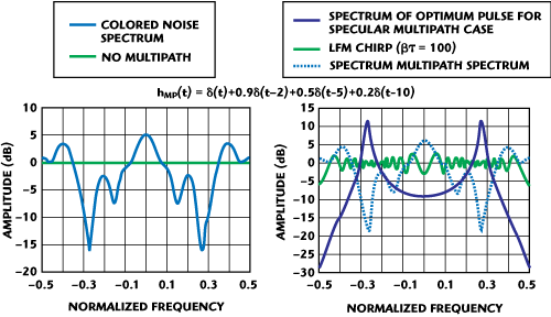
Figure 5 Comparison of a non-adaptive (LFM) waveform and the optimum solution tailored to the interference spectrum.5
Knowledge-Aided Processing for Enhanced Real-Time Adaptivity
Beginning in 2001, the Defense Advanced Research Projects Agency (DARPA), in collaboration with the Air Force Research Laboratory (AFRL), initiated the Knowledge-Aided Sensor Signal Processing and Expert Reasoning (KASSPER) project with the goal of developing the first knowledge-aided (KA) real-time high performance embedded computing (HPEC).5 Building on some of the pioneering work in knowledge-based and expert reasoning conducted at the AFRL’s Rome Air Development Center (RADC),11-13 the KASSPER project expanded the algorithmic capabilities of KA processing and implemented a real-time version of KA STAP (space-time adaptive processing).14
STAP in real-world environments is particularly vulnerable to complex clutter environments due to its need to estimate a generally high dimensional space-time (such as angle-Doppler) covariance matrix. Using the “RMB Rule” (Reed, Mallett, Brennan)15 to achieve a reasonable covariance estimate, an order of two times (2X) the dimension of the space-time receive vector is required for the number of independent and identically distributed (i.i.d.) training samples. For an eight element adaptive antenna, utilizing four Doppler channels (jointly), this results in the need for at least 32 i.i.d. samples. In most conventional STAP implementations, these samples are achieved by selecting 32 (or more) adjacent range bins to the range cell of interest. Dense target environments, highly heterogeneous terrain, urban clutter and other large clutter discretes can significantly degrade performance of a sample covariance based implementation of STAP.6

Figure 6 Example of the effectiveness of indirect KA methods with real data.
KA methods can overcome these issues by utilizing other information sources besides the incoming radar data stream. For example, it has been shown that digital terrain and land cover maps, SAR imagery (complex), and even prior measurement histories, can all be utilized to improve the estimation of the interference channel5—with commensurate improvements in radar performance. Generally, the incorporation of other knowledge sources into the adaptive filtering process is either direct or indirect. For example, an indirect method consists of a judicious selection of both the available training data and filter structure. Terrain and land cover maps are especially useful for this method as they can identify roadways, abrupt changes in terrain (such as land-sea interfaces), etc.
An example of the improvement achievable using an intelligent screening of the training data is displayed in Figure 6. In this example, using AFRL’s Multi-Channel Airborne Radar Measurement (MCARM) system, an airborne target becomes detectable after knowledge-aided training is applied to the STAP weights. In this particular example, competing ground traffic was causing a broadening of the angle-Doppler clutter notch.16
Direct methods of prior knowledge incorporation are generally more complex and difficult to implement, but can yield significantly improved performance in demanding environments. One example, grounded in the incorporation of “prior” information as formulated by Bayes,17 is to combine an estimate of the underlying clutter covariance matrix R obtained from prior knowledge sources Ro, with an estimate Rd obtained using the incoming data stream. For example, under fairly general conditions, this KA estimate RKA has the form

where typically α, β satisfy 0 ≤ α £ 1 and ≤ = 1 – α. The above was shown to be the optimum Bayesian estimate of the true underlying covariance R when Ro and Rd are statistically independent estimates (the weighting coefficients are simply proportional to the effective amount of training data used to form each constituent covariance estimate, respectively).5 Figure 7 shows an example of the performance improvements achievable using this type of direct method when applied to the 6th KASSPER data challenge set.18 In this case, the prior knowledge source was a combination of digital terrain maps and an efficient electromagnetic propagation model. However, another extremely useful information source is SAR imagery, which is essentially a high resolution clutter map and thus ideally suited for creating KA priors.5

Figure 7 An example of the effectiveness of a direct KA methods when applied to the 6th KASSPER Challenge data set. 18
One of the biggest obstacles facing the DARPA/AFRL KASSPER project was not developing algorithms that could show the utility of incorporating other knowledge sources, but rather developing a real-time HPEC architecture that could overcome the inescapable latency associated with “retrieving data (knowledge) from memory”. Somewhat surprisingly, the solution turned out to be relatively straightforward once an overall system engineering perspective was adopted relative to the types of radars involved.
The crux of the idea is this: The problem is accessing the environmental dynamic database (EDDB), which typically resides in some mass storage (such as RAID) configuration. This access cycle can take orders of magnitude more time than is required to keep up with real-time radar signal throughput timescales.5

Figure 8 Real-time KASSPER HPEL system developed by MIT Lincoln Laboratories.
However, this is where physics and engineering come in. If it were possible to know where the radar will be and what it will be doing, just a second or so in the future, a “look ahead” parallel processor (it is actually the KA coprocessor of Figure 2), could begin the retrieval of relevant data and make any necessary adjustments (indirect or direct) to the baseline adaptive processing chain.5 As it turns out, this assumption is perfectly justified in practice since: (1) An extremely accurate estimate (to within the radar’s resolution) of the radar’s position is typically available for many seconds into the future simply due to Newtonian physics; and (2) The radar scheduler is highly deterministic on the order of seconds (even longer in many cases). Thus, one can know where the radar will be, and what the radar will be doing far enough into the future to overcome the memory retrieval issues associated with KA processing. Indeed just such a real-time KASSPER architecture was built and demonstrated by MIT Lincoln Laboratories and displayed at DARPATech 2004 (see Figure 8).19
Putting it all Together: Cognitive Radar
This article briefly introduces an emerging new adaptive sensor paradigm born out of two major radar advancements, transmit diversity/adaptivity, coupled with KA processing. When combined, an architecture emerges that can demonstrate all of the key attributes of a truly “cognitive” system. While radar was the focus of this article, it is hoped that other sensor and communication systems will benefit as well from a knowledge-aided, fully adaptive cognitive architecture.
References
- S. Haykin, “Cognitive Radar: A Way to the Future,” IEEE Signal Processing Magazine, Vol. 23, No. 1, January 2006, pp. 30-40.
- J.R. Guerci, Cognitive Radar: The Knowledge-aided Fully Adaptive Approach, Artech House, Norwood, MA, 2010.
- Definition of Cognition, National Institutes of Heath, National Institute of Mental Health, http://scienceeducation.inh.gov/supplements/nih5/Mental/other/glossary.htm.
- M.A. Richards, Fundamentals of Radar Signal Processing, McGraw-Hill, New York, NY, 2005.
- J.R. Guerci and E.J. Baranovski, “Knowledge-aided Adaptive Radar at DARPA: An Overview,” IEEE Signal Processing Magazine, Vol. 23, No. 1, January 2006, pp. 41-50.
- W.L. Melvin, “Space-time Adaptive Processing and Adaptive Arrays: Special Collection of Papers,” IEEE Transactions on Aerospace and Electronic Systems, Vol. 36. No. 2, 2000, pp. 508-509.
- J.R. Guerci, “Knowledge-aided Sensor Signal Processing and Expert Reasoning (KASSPER),” First Annual DARPA KASSPER Workshop Proceedings, Washington, DC, 2002.
- A.V. Oppenheim and R.W. Shafer, Discrete Time Signal Processing, Third Edition, Prentice-Hall, New York, NY, 2009.
- H.L. Van Trees and E. Detection, Modulation Theory, Part II, John Wiley & Sons Inc., Somerset, NJ, 1971.
- G. Strang, Introduction to Linear Algebra, Wellesley Cambridge Press, Wellesley, MA, 2003.
- V. Vannicola, et al., “Expert System for Sensor Resource Allocation [Radar Applications],” 1990 IEEE Midwest Symposium on Circuits and Systems Proceedings, pp. 1005-1008.
- V.C. Vannicola and J.A. Mineo, “Applications of Knowledge-based Systems to Surveillance,” 1988 National Radar Conference Proceedings, pp. 157-164.
- M. Wicks, et al., “Expert System Constant False Alarm (CFAR) Processor,” US Patent 5,499,039, 1996.
- J.R. Guerci, Space-time Adaptive Processing for Radar, Artech House, Norwood, MA, 2003.
- I.S. Reed, J.D. Mallet and L.E. Brennan, “Rapid Convergence Rate in Adaptive Arrays,” IEEE Transactions on Aerospace and Electronic Systems, Vol. AES-10, No. 6, 1974, pp. 853-863.
- W. Melvin, et al., “Knowledge-based Space-time Adaptive Processing for Airborne Early Warning Radar,” IEEE Aerospace and Electronic Systems Magazine, Vol. 13, No. 4, 1998, pp. 37-42.
- T. Bayes, “An Essay Towards Solving a Problem in the Doctrine of Chances,” Philosophical Transactions of the Royal Society of London, Vol. 53, p. 1763.
- J.S. Bergin, et al., “STAP with Knowledge-aided Data Pre-whitening,” 2004 IEEE Radar Conference Proceedings, pp. 289-294.
- DARPATech 2004, http:// www.darpa.mil/DARPATech2004/.

Joseph R. Guerci is a graduate of Polytechnic University with a PhDEE degree in System Engineering. He has held adjunct professorships in engineering and applied mathematics at The City University of New York, Polytechnic University, The Cooper Union for Advancement of Art and Science, and Virginia Tech. Additionally, he has held senior engineer and scientist positions in industry and was recently Chief Technology Officer (CTO) for SAIC’s Research, Development, Test & Evaluation (RDT&E) Group. He has over 25 years of experience in advanced technology research and development in government, industrial and academic settings. His government service included a recent seven-year term with the Defense Advanced Research Projects Agency (DARPA) in which he held the positions of Program Manager, Deputy Office Director and finally Director of the Special Projects Office (SPO). In these capacities, he was involved in the inception, research, development, execution and transition of next generation multidisciplinary defense technologies.