
Mobile-TV is poised to become the next great mobile accessory, with analysts projecting that 50 million digital-TV-ready mobile handsets will ship in 2009.1 For designers, making this task a reality is somewhat daunting, given the significant user-experience complexities that mobile-TV introduces, such as battery life, reception and range, screen size and picture quality.
While these challenges are sure to be overcome, the impact on the antenna is often overlooked in the early planning stages. Designers soon realize the challenges involved with supporting a wide range of voice and data frequencies in the same device as a mobile-TV antenna that must span 470 to 862 MHz. Inevitably, RF tunable technologies are required in order to keep embedded mobile-TV antennas on track, but which technologies are robust enough to handle the job?
If an antenna is constrained to a small form factor, it cannot receive all of the required mobile-TV bands at high efficiency without some sort of reliable tuning technology. Because they could not cover the wide mobile-TV frequency range with a traditional embedded antenna, designers of the first mobile-TV handsets used a traditional external whip antenna (see Figure 1).

Figure 1 Initial mobile-TV handsets required use of an external whip antenna.
The challenges to using a whip antenna like the one shown in Figure 1 occur on two fronts. Most importantly, it is a potential point of failure because of repeated handling by the end user and other external forces that can cause damage. Additionally, because mobile-TV applications are so new, handset manufacturers generally have adopted a “push” marketing strategy; they have added this functionality in anticipation that consumers will eventually use it (much like with Bluetooth). However, including an awkward external whip antenna to support a function that the user might not use may be counter-productive to generating demand for that model. What is needed is a new design scheme for an antenna that can span 400 MHz mobile-TV and still be embedded into a handset.
Mobile-TV Antenna Challenges
Mobile-TV applications such as DVB-H and ISDB-T require adding very broadband reception and delivering good coverage to an already complex system, all in a small space. According to the European Telecommunications Standards Institute (ETSI) Technical Report “DVB-H Implementation Guidelines,” it is very difficult to design a high-performance antenna for the UHF band mobile-TV. Because the handset is very small compared to the wavelength, typical antenna gain for handheld terminals is –10 dBi at 474 MHz increasing to –5 dBi at 858 MHz. This means that the antenna loses 10 dB of power at the low end of the band. Also, guaranteeing a good input match across the whole UHF-IV/V band (470 to 862 MHz) is challenging, and is likely to require a tunable matching circuit.2
To date, designers have typically had only two antenna choices: a passive internal antenna with poor performance, or the external whip antenna, which many consumers view as archaic. For future designs, however, the embedded, internal antenna is demanded by the market; therefore, some type of antenna tuning is critical in order to ensure a good user experience. While mobile-TV is a fairly new service, it is experiencing market penetration in Europe (DVB-H) and Japan (ISDB-T),3 so providers are becoming motivated to find a suitable antenna tuning technology to support it.
For mobile-TV applications, the achievable bandwidth and input match is directly related to the physical size of the antenna and the mobile phone. For this reason, most traditional internal mobile-TV antennas have very poor performance; radiation efficiency suffers, and voltage standing wave ratio (VSWR) gets very high (easily 6:1 across the 470 to 862 MHz bandwidth). This causes the receiver to lose 3 dB of sensitivity simply due to the antenna mismatch, which for the mobile-TV functionality would significantly reduce the range and degrade reception quality.

Figure 2 Input VSWR of a traditional DVB-H antenna (a) and tubable internal antenna (b).
As a result of these performance issues, interest in a “tunable” internal antenna that could cover a narrow section of the bandwidth—one that can be “retuned” as the receive channel changes—is increasing. This would deliver significantly better VSWR making sure that most of the signal power captured by the antenna actually ends up in the receiver. With this tunable architecture, the frequency of the antenna resonance could be moved up and down as needed in order to match the desired channel. Figure 2 shows the input impedance of an embedded mobile-TV antenna with fixed matching (2a) and with a tunable matching circuit (2b). Note the VSWR of the antenna without tuning is 6:1, and with tuning circuitry the matching is very good at better than 2:1 across the whole band.
Because mobile-TV is a receive-only system, the open-loop antenna tuning method must be used, in which the center frequency of the antenna is tuned based on a look-up table for the tunable component as a function of the desired receive frequency. The antenna center frequency is shifted as necessary in order to cover specified frequencies within the 470 to 862 MHz range, and the tuning technology quickly retunes the antenna as the receive channel is changed. In effect, the manufacturer sets the antenna element to cover a small section of the band, and the tuning element moves this window around. The UHF band for DVB-H is divided into 48 channels 8 MHz apart. Typically 16 or 32 tuning states will be required to give fine resolution to tune the narrow-band antenna element to any channel in the mobile-TV band and to enable high-quality reception.
GSM/DVB-H Interoperability Power Handling Requirements
When there is a mobile-TV antenna and a GSM cellular antenna embedded in the same phone, the tuning element for the mobile-TV antenna has to be able to handle high levels of coupled GSM power. For example, the isolation between the GSM and the DVB-H antennas inside a mobile phone can be as low as 7 dB, and GSM antennas transmit at power levels up to +33 dBm. As a result, when the GSM transmitter is transmitting at full power, the tuning element might actually see coupled power levels near +26 dBm. Unless the tuning circuitry can withstand these high power levels, the coupled power can modulate it and change the center frequency of the mobile-TV antenna or generate a high level of harmonics in the tuning element.
To address this problem, one might consider simply switching off the GSM transmitter when the mobile-TV receiver is engaged, or employ time-scheduling methods to prevent collisions between the two modes. However, the GSM phone has to transmit periodic location updates to the base station, causing disruptions in mobile-TV reception.
In some countries, the handset also needs to send billing information over the cellular line when the user is watching TV, or the user might receive a phone call while the TV is on. A tuning method that allows simultaneous operation of GSM and mobile-TV is thus highly desirable, but imposes a very challenging power handling constraint for the antenna tuning element.
Mobile-TV Antenna Tuning Design Options

Table 1 Key Requirements for Tunable Elements for Mobile-TV Antenna Tuning
What is needed is an antenna tuning technology that can handle more than +26 dBm of coupled GSM power in order to keep mobile-TV on track with an embedded antenna. Since it is connected to the antenna, the tuning circuit also needs to be extremely linear so as not to generate harmonics or inter-modulation distortion. The tunable element, such as variable capacitor, needs to have a tuning ratio of at least 3:1 or better. In addition, the whole circuit must have power consumption of less than 1 mA. Finally, the tuning circuitry must be small, rugged and reliable. It needs low insertion loss and a high quality factor (Q) (see Table 1).
Varactor Diodes
Sometimes a varactor diode approach is proposed for mobile-TV antenna tuning, since it is a straightforward and fairly inexpensive solution. Since varactor diodes are analog components, they require a dedicated analog tuning voltage output for the mobile-TV chipset. However, varactor diodes cannot typically meet the high power handling and linearity requirements to support the GSM/DVB-H interoperability by allowing simultaneous GSM and DVB-H operation.
Switch-based Tuning
Since varactor diodes cannot handle the power requirements of embedded mobile-TV antenna tuning, a “brute force” approach of switch-based tuning, such as using a GSM SP4T switch with a tuning circuit on each of the four legs of the switch, has been developed. This approach provides very coarse tuning, which may not be sufficient to guarantee good performance across the whole band.
FET Switched Capacitor Banks
FET Switched Capacitor Banks based on bulk CMOS technology showed early promise as the technology to satisfy this challenging list of requirements for mobile-TV antenna tuning.4 They have a high quality factor, but their linearity is typically on the order of IIP3 =+25 dBm, which suggests less than +15 dBm of power handling. Even though this is high enough for receiving the mobile-TV signal itself, it cannot support simultaneous operation of GSM and DVB-H in the same handset. However, compared to bulk CMOS FETs, Peregrine’s UltraCMOS™ FETs have the fundamental advantage of stacking due to the fully insulating sapphire substrate, making it possible to use multiple low-voltage FETs in series to handle the high power signals encountered in GSM and WCDMA operation.
DuNE™ Technology: A New Antenna Tuning Solution

Figure 3 DuNE DTC device schematic (top) and packaged in 2 x 2 mm 8L DFN (bottom).
DuNE™ Technology, a patent-pending design methodology made possible by the UltraCMOS process and HaRP™ design innovations, has enabled the tunable capacitor circuit—referred to as a Digitally Tunable Capacitor (DTC)—which can handle the GSM/DVB-H interoperability requirements. DTCs designed for mobile-TV applications can be housed in a 2x2 mm package with a built-in 3-wire serial interface (see Figure 3).
Figure 4 Measured capacitance as a function of state for a DuNE DTC.
Initial DuNE DTCs have been designed for 5 bits of resolution or 32 tuning states, which provides the level of fine resolution that is required to tune the antenna across the entire mobile-TV band. Figure 4 shows the 1.36 to 6.3 pF capacitance range (4.6:1 tuning ratio) for a 5-bit mobile-TV DuNE DTC.

Figure 5 Measured quality factor as a function of state for a DuNE device.
Low losses for the tunable element are very important in reducing the insertion loss for the tunable matching network and optimizing the total antenna efficiency. The mobile-TV DuNE DTC has been designed for Q = 40-70 at 470 to 862 MHz (see Figure 5). The current consumption for the device is only 11 μA at +2.75 V.
Figure 6 Measured DTC IIP3 and power handling as a function of state.
Due to the fundamental advantages of UltraCMOS,5 such as perfectly insulating sapphire substrate and highly linear FETs, DuNE technology can be scaled to handle any power level without degrading Q or tuning ratio, simply by changing the number of FETs in the stack. As a result, it can be scaled to handle power levels anywhere from +20 to +40 dBm and higher. For mobile-TV applications, DuNE DTCs have been designed for +28 dBm nominal power handling and GSM/WCDMA applications, power handling is better than +38 dBm. Figure 6 shows IIP3 > +62 dBm and better than +28 dBm power handling measured at 900 MHz for the moblie TV DuNE DTC. It is also noteworthy that all performance parameters of the DTC (capacitance range, tuning ratio, quality factor, power handling) can be changed by circuit design instead of materials engineering, enabling rapid time to market.
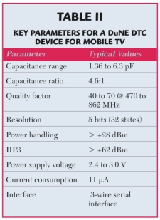
Table 2 Key Parameters for a DuNE DTC Device for Mobile-TV
Because they are manufactured on the UltraCMOS process, the new DuNE DTC products can integrate the digital functions (CMOS control, digital processing, serial peripheral bus, tuning algorithm), analog functions (mismatch sensors, charge pumps, biasing circuitry), as well as RF passive (high Q capacitors) and RF active (switches, ESD protection) circuitry in addition to the DTC core. See Table 2 for a list of the key parameters for mobile-TV.
The Future of Mobile-TV Antenna Tuning
DuNE technology addresses the required performance points for embedding a tunable mobile-TV antenna. These self-contained RFIC solutions communicate directly with the mobile-TV receiver chipset and integrate a digital communication interface and all the other required functionality monolithically on the die, which simplifies implementation as well as minimizes lines/connections between the two devices. High-performance, compact, and simple antenna tuning solutions, proven process technologies, and high-volume capability are critical to the successful adoption of complex mobile-TV products. Mobile handset designers now have a way to successfully design in tunable embedded antennas for mobile-TV, and uncover new market opportunities.
References
1. Strategy Analytics, September 2007.
2. ETSI TR 102 377 V1.2.1 (2005-11), section 10.4.
3. I. Chan, “Is Asia Mobile-TV’s Biggest Market?, ZDNet Asia, http://www.zdnetasia.com/news/communications/0,39044192,39368083,00.htm.
4. P. Sjoblom and H. Sjoland, “Measured CMOS Switched High-quality Capacitors in a Reconfigurable Matching Network, IEEE Transactions, Vol. 54, No. 10, October 2007, pp. 858-862.
5. “UltraCMOS™ Process Technology,” http://www.psemi.com/content/foundry/foundry_process_tech.html.