Until recently, conventional commercial antennas in the worldwide market have been external ones, because they provide omni-directional radiation patterns for optimum coverage in all circumstances. In addition, stubby antennas are shorter, more robust and, arguably, more aesthetically appealing than the retractable antenna.
Most of the stubby antennas reported are of the helical type or a modified one.1–6 A meander-type structure is generally used in monopole antennas due to its simplicity and adaptability to miniaturization. However, meander line antennas are often limited by a narrow impedance bandwidth.
To achieve broadband characteristics, the proposed antenna incorporates vertical lines in a meander line antenna (MLA). A parametric study has been carried out using HFSS software.
The proposed antenna, which has omni-directional radiation characteristics and operates in the DCS (1.71 to 1.88 GHz), PCS (1.85 to 1.99 GHz), UMTS (1.92 to 2.17 GHz), WiBro (2.3 to 2.4 GHz) and WLAN (2.45 to 2.485 GHz) bands, has potential applications in mobile terminals and repeaters. Details of the antenna design and the experimental results obtained are presented and discussed in the subsequent sections of this article.
Antenna Design
An MLA has a high current density in accordance with geometrical characteristics; therefore, its operating impedance bandwidth is generally narrow. A representative method to extend the impedance bandwidth is to widen the surface area of an antenna and thereby broaden its current distribution. The proposed monopole antenna incorporates vertical lines within the MLA to broaden the current distribution. As a result, the proposed antenna has an extended impedance bandwidth.

The geometry of the proposed antenna is shown in Figure 1. It consists of the MLA and the vertical lines A, B and C. The dimensions of the MLA, which are optimized to operate in the DCS to WLAN bands, are as follows: the width of the meander is Wa = 8 mm, the pitch S = 2 mm and the width of the line w = 0.7 mm. Each vertical line is located so as to divide the meander section into three equal parts; the distance between each vertical line is 1.733 mm.
Additionally, each vertical line has a width equal to the line width of the antenna (w). The antenna is printed on an FR-4 substrate with a thickness t = 0.8 mm and a relative permittivity εr = 4.6. The external dimensions of the antenna are 8 x 18.9 x 0.8 mm. The ground plane, with dimensions 40 x 50 mm, can be considered to be the circuit board of a practical mobile terminal.
The antenna is excited through a coaxial probe. There is a gap of 2.2 mm between the antenna and the ground plane. This gap is usually required for a monopole above a ground plane in order to achieve good impedance matching.
Discussion and Experimental Results

To design the proposed antenna, the simulation was carried out using Ansoft High-Frequency Structure Simulator (HFSS) simulation software to understand the behavior of the antenna model and determine the suitable parameters.
Figure 2 shows the configurations of the antennas studied. The return loss versus frequency of the MLAs, when the vertical lines A, B and C are added, is shown in Figure 3. Table 1 lists the performance of the antennas. It is seen that for Antenna 4, which is the proposed antenna, a bandwidth of 38.66 percent (approximately 810 MHz, from 1.69 to 2.5 GHz) is achieved, which covers the DCS, PCS, UMTS, WiBro and WLAN bands. This bandwidth is greater than the 32.91 percent of Antenna 3 and much greater than the 17.42 percent of Antenna 2.

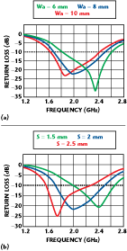
This behavior is largely due to the much broader current distribution that was achieved in the antenna. The proposed antenna is a modified MLA. Therefore, the operating frequencies are basically determined by the values of Wa and S.7 Figure 4 shows the return loss for the antenna with various widths (Wa) and pitches (S).
Table 2 shows the performance of the antennas. By varying Wa from 6 to 10 mm, while maintaining S = 2 mm, the center frequency can be decreased from 2.225 to 2.025 GHz and the impedance bandwidth is not varied. By varying S from 1.5 to 2.5 mm, while maintaining Wa = 8 mm, the center frequency can be decreased from 2.32 to 1.855 GHz and the impedance bandwidth is increased from 720 to 910 MHz.
The significant reason for the decrease in the impedance bandwidth, and the increase in the operating frequency exhibited when the meander sections are brought closer together, becomes evident when examining the current vectors on the radiating elements.8,9
The antenna was fabricated and measured using an Anritsu 37325A network analyzer. The measured and simulated return loss for the aforementioned dimensions are shown in Figure 5. Good agreement between the simulated and measured results is achieved. The predicted and measured 10 dB return loss bandwidths are 38.66 percent (1.69 to 2.5 GHz) and 38.22 percent (1.704 to 2.509 GHz), respectively. The radiation characteristics of the proposed antennas were also measured using STARGATE 32.

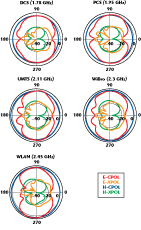
Figure 6 plots the measured radiation patterns at 1.78 (DCS), 1.95 (PCS), 2.11 (UMTS), 2.3 (WiBro) and 2.45 (WLAN) GHz, respectively. It is important to note that the radiation patterns are shown in four planes: vertical and horizontal polarizations in both the E- and H-planes. The patterns obtained were generally close to monopole-like patterns. The maximum gain of the proposed antenna, shown in Figure 7, is 2.78 dBi at 2.11 GHz. The gain variations are less than 1.86 dBi for each of the operating frequencies.
Conclusion
A novel broadband meander line monopole antenna with vertical lines for the DCS, PCS, UMTS, WiBro and WLAN bands has been proposed and investigated. The proposed antenna has compact dimensions of 8 x 18.9 x 0.8 mm. The obtained 10 dB return loss bandwidth is 38.22 percent (805 MHz) and the measured maximum gain is 2.78 dBi.

The radiation patterns are similar to those of a monopole antenna. These features make the proposed antenna attractive for mobile terminals and repeater applications.
References
1. H. Nakano, N. Ikeda, W.Y. Yuan, R. Suzuki, H. Mimaki and J. Yamauchi, “Realization of Dual Frequency and Wideband VSWR Performance Using Normal-model Helical and Inverted-F Antennas,” IEEE Transactions on Antennas and Propagation, Vol. 46, No. 6, June 1998, pp. 788–793.

2. S.C.K. Ko and R.D. Murch, “A Diversity Antenna for External Mounting on Wireless Handsets,” IEEE Transactions on Antennas and Propagation, Vol. 49, No. 5, May 2001, pp. 840–842.
3. J.C. Louvigne and A. Sharaiha, “Broadband Tapered Printed Quadrifilar Helical Antenna,” Electronic Letters, Vol. 37, 2001, pp. 932–933.
4. P. Eratuuli, P. Haapala and P. Vainikainen, “Dual Frequency Wire Antennas,” Electronic Letters, Vol. 32, 1996, pp. 1051–1052.
5. O. Leisten, J.C. Vardaxoglou, P. McEvoy, R. Seager and A. Wingfield, “Miniaturized Dielectrically-loaded Quadrifilar Antenna for Global Positioning System (GPS),” Electronic Letters, Vol. 37, 2001, pp. 1321–1322.
6. D.U. Sim, J.I. Moon and S.O. Park, “A Wideband Monopole Antenna for PCS/IMT-2000/Bluetooth Applications,” IEEE Antennas and Wireless Propagation Letters, Vol. 3, 2004, pp. 45–47.

7. T. Endo, Y. Sunahara, S. Satoh and T. Katagi, “Resonant Frequency and Radiation Efficiency of Meander Line Antennas,” Electronics and Communications in Japan, Part 2, Vol. 83, No. 1, 2000.
8. S.R. Best and J.D. Morrow, “The Effectiveness of Space-filling Fractal Geometry in Lowering Resonant Frequency,” Antennas and Wireless Propagation Letters, Vol. 1, 2002, pp. 112–115.
9. S.R. Best, “On the Performance Properties of the Koch Fractal and Other Bent Wire Monopoles,” IEEE Transactions on Antennas and Propagation, Vol. 51, 2003, pp. 1292–1300.
