
Orthogonal frequency division multiplexing (OFDM) is a multi-carrier transmission technique whose history dates back to the mid-1960s. Although the concept of OFDM has been around for a long time, it has only recently been recognized and adopted as an effective technique for high speed bi-directional wireless data transfer. WiMAX, DAB and DVB-T are some of the new emerging standards that use OFDM. This is because of the following reasons: First, OFDM is very immune to channel imperfections; second, OFDM uses bandwidth very efficiently, that is it uses less bandwidth than traditional modulation schemes to transmit at a particular rate; lastly, OFDM can be implemented using DSP techniques on fast and low cost embedded devices, which have become easily available over the last few decades.
A General Overview of OFDM and its Generation
OFDM spreads the data to be transmitted over a large number of carriers—typically in the range of 50 to 1000, but sometimes in thousands. For example, DVB-T has options for using either 1705 or 6817 carriers. The effective data rate to be conveyed by each of these carriers is therefore correspondingly reduced. They have equal, precisely chosen, frequency spacing. This is the reciprocal of the duration, called the active symbol period, over which the receiver will examine the signal.
This choice of carrier spacing ensures orthogonality (the ‘O’ in OFDM) of the carriers. The demodulator for one carrier does not ‘see’ the other carriers even though there is no explicit filtering and their spectra overlap. There is therefore no crosstalk between carriers. Fortunately, what seems to be a very complex process of modulating (and demodulating) hundreds of carriers simultaneously is equivalent to a discrete Fourier transform operation, for which efficient fast Fourier transform (FFT) algorithms exist. Integrated circuit implementations of OFDM modulators and demodulators are thus feasible for affordable mass-produced transmitters and receivers.
To generate OFDM, the relationship between all the carriers must be carefully controlled to maintain the orthogonality of the carriers. For this reason, OFDM is generated by first choosing the spectrum required, based on the input data and modulation scheme used. Each carrier to be produced is assigned some data to transmit. The required amplitude and phase of the carrier is then calculated based on the modulation scheme (typically BPSK, QPSK, or QAM). The spectrum is constructed using the calculated amplitudes and phases of the carriers. The required spectrum is then converted back to its time domain signal using an inverse Fourier transform.
In most applications, an inverse fast Fourier transform (IFFT) is used. The IFFT performs the transformation very efficiently, and provides a simple way of ensuring that the carrier signals produced are orthogonal. The FFT transforms a cyclic time domain signal into its equivalent frequency spectrum. The IFFT performs the reverse process, transforming a spectrum (amplitude and phase of each component) into a time domain signal. An IFFT converts a number of complex data points, which represent a signal in the frequency domain, into the equivalent time domain signal with the same number of points.
Each data point in the frequency spectrum used for an IFFT is called a bin. The orthogonal carriers required for the OFDM signal can be generated easily by setting the amplitude and phase of each frequency bin, then performing the IFFT. Since each bin of an IFFT corresponds to the amplitude and phase of a set of orthogonal sinusoids, the process guarantees that the carriers generated are orthogonal. This is explained in more detail in the next section. A further refinement adds a guard interval to each OFDM symbol. Each modulated carrier is transmitted for a total symbol period, which is longer than the active symbol period by a period called the guard interval. This means that the receiver will experience neither inter-symbol nor inter-carrier interference, provided that any echoes present in the signal have a delay that does not exceed the guard interval.
Naturally, the addition of the guard interval reduces the data capacity by an amount dependent on its length. The concept of a guard interval could in principle be applied to a single-carrier system, but the loss of data capacity would normally be prohibitive. However, with OFDM, the loss of data capacity is not so high due to the presence of many carriers. The insertion of guard time is also called cyclic prefix insertion.
The Use of OFDM in Modern Communication Systems
Most present day communication systems transmit signals over wireless channels that are far from ideal. Due to OFDM’s immunity to many channel imperfections, it is the ideal modulation scheme for many applications that transmit signals in hostile environments. By dividing the channel into many narrowband flat fading channels, OFDM makes it easier to reverse the effects of frequency selective fading. This is because fades can be evaluated and reversed in each of the narrowband channels where it can be assumed to be constant. Also, OFDM effectively eliminates intersymbol interference (ISI) by inserting the cyclic prefix.
Given OFDM’s bandwidth efficiency and the fact that it can be easily implemented on embedded devices, OFDM has found wide spread use in wireless communication systems. As a specific example, consider 802.11a (WiFi), which uses OFDM in the physical layer. It uses 64 orthogonal carriers and a cyclic prefix, which is at most one quarter of the length of the OFDM symbol. Four modulation schemes are supported: BPSK, QPSK, 16-QAM and 64-QAM. Not all the 64 carriers are used for data transmission. Some of them are always zero (these serve as the guard band) and some carriers always carry known data. These carriers are called pilots and are used to estimate the effects of the channel. In the following section, the working of an OFDM system is considered in more detail. The mathematics presented is not meant to be a formal proof of concepts. It is meant to provide an intuitive understanding of the working of an OFDM system.
The Theory of OFDM
Orthogonality of Carriers
As stated earlier, orthogonality of carriers is a necessary condition for the proper functioning of an OFDM system. Two functions f(x) and g(x) are said to be orthogonal in the period [a, b] if

Physically, if f(x) and g(x) are signals, then the left-hand side of Equation 1 is a measure of how much common energy the spectra of these two signals have. In the case of OFDM, the carriers are sinusoidal. Consider two sinusoidal functions ej2πmft and ej2πnft. Then
Equation 2 shows that all harmonics of a sinusoid of frequency f are orthogonal to each other. This property is used in the generation of orthogonal carriers for OFDM signals.
Generation and Demodulation of an OFDM Signal
The OFDM signal is formed by modulating these orthogonal carriers using a sequence of symbols generated by mapping the input bit stream into complex symbols (IQ symbols) based on an m-ary constellation. By doing this, the bit stream is reduced to a sequence of complex symbols. The OFDM symbol, formed by modulating N orthogonal sinusoidal carriers using N symbols generated by mapping the input bit stream, is given by
Given this representation of an OFDM symbol and the fact that all the carriers are orthogonal to each other, all that needs to be done at the receiver to recover a symbol that was used to modulate a particular carrier, say the ith harmonic of the fundamental frequency, is to perform an “integrate and dump” demodulation at that carrier frequency.
Equation 4 shows that symbols can be extracted from the carriers they modulate even though the spectra of the carriers overlap. In discrete time, the OFDM symbol s(t) in Equation 3 can be represented as

where T (the active symbol period in continuous time) has been replaced by N and t (continuous time) has been replaced by n (discrete time). Equation 5 can be identified as the inverse discrete Fourier transform (IDFT). Thus, the IDFT can be used to generate an OFDM symbol from a sequence of IQ symbols. Similarly, by replacing T by N, t by n and the integral by a summation in the “integrate and dump” equation, one obtains

where  is the estimate of the symbol modulating the carrier whose frequency is i times the fundamental frequency. Equation 6 is the discrete Fourier transform (DFT). Thus, the DFT can be used to demodulate OFDM signals.
Guard Interval or Cyclic Prefix Addition
Consider the transmission of the simple OFDM symbol, which was described earlier. Here, carriers exist only within the OFDM symbol duration T (which is also the correlation period). If the channel has a frequency selective delay, some carriers may be received later than others. This would lead to a situation where some carrier will have a zero amplitude for some part of the correlation interval.
For the orthogonality between any two received carriers to be preserved, every carrier must have an integer number of cycles in the correlation (integration) interval. To counter the effect of delay on the orthogonality of the carriers, each of the carriers is extended in time. This is called cyclic prefix or guard interval insertion. The duration of extension is decided based on the root mean squared delay spread of the channel.
Another advantage of inserting the cyclic prefix is that the effect of the channel transfer function reduces from a linear convolution (of the signal and the transfer function) to a cyclic convolution. Since a DFT is being used at the demodulator, and the effect of the channel is a circular convolution, the effect of the channel can be equalized by dividing the DFT by the channel transfer function estimate. This is because the circular convolution of two functions is the product of their DFTs. Figure 1 shows the cyclic extension of two orthogonal OFDM carriers.
Spectrum of an OFDM Signal
Consider a simple mapping of one bit onto one carrier. The bit is represented by the presence or absence of the carrier in the OFDM symbol interval T. In the time domain, the OFDM symbol is a sum of N orthogonal sinusoids multiplied by a rectangular pulse of duration T.


The spectrum of the carriers is a set of impulses and the spectrum of the square pulse is a sinc function. The OFDM symbol spectrum is therefore a convolution of the above-mentioned spectra.
This is a sum of shifted, weighted sinc functions. The sinc function is defined as

Figure 2 shows the spectrum of an individual carrier in the OFDM signal and the spectrum of the OFDM signal itself.
Basic OFDM Transmitter
Putting together the various operations explained previously, the block diagram of a basic OFDM transmitter may be drawn, as shown in Figure 3. After the addition of the guard interval, the symbol-shaping block interpolates and low pass filters the basic OFDM signal generated. The output of this stage is the complex baseband of the OFDM signal. This needs to be up-converted to IF by an IQ modulator and then up-converted to RF frequency before it is transmitted.
Writing a Simple OFDM Application with LabVIEW and Modulation Toolkit
This section describes the implementation of each of the blocks shown in the OFDM transmitter block diagram. In addition, forward error correction (FEC) is also described.
Forward Error Correction
Even though error correction is strictly not a part of the OFDM system itself, every system that uses OFDM needs some form of forward error correction (FEC) to achieve reasonable bit error rates (BER). Modulation Toolkit (MT) provides several error-coding options. Therefore, to incorporate FEC into an OFDM application in LabVIEW, one just needs to drop the appropriate virtual instrument (VI) from the Modulation Toolkit error-coding palette (see Figure 4). Modulation Toolkit has the following error coding options: Reed-Solomon, Golay, Hamming, BCH and Convolutional encoders.
Mapping Bits to Symbols
In an OFDM system, bits are mapped to complex (IQ) symbols, which are then used to modulate one carrier in the OFDM symbol, that is the IQ symbol decides the phase and/or amplitude of the carrier. Bits are converted into IQ symbols by mapping sets of bits onto points on the IQ plane based on an m-ary symbol map. Modulation Toolkit provides a VI, which converts a stream of bits to a stream of complex symbols based on a symbol map, which may either be one used for a standard IQ modulation scheme or a user defined one.
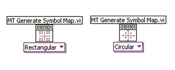
Figure 5 shows how a bit stream may be mapped to complex symbols based on a standard m-ary QAM constellation. Custom symbol maps may also be generated and used to map bits to symbols. Custom maps may either be rectangular (such as m-QAM) or circular (such as m-PSK). Figure 6 shows that the polymorphic VI may be used to generate arbitrary symbol maps. The symbol map output of the VI needs to be wired to the MT Map Bits to Symbols VI as in the previous case.
Interleaving Bits/Symbols

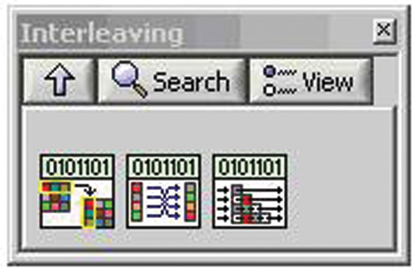
Many applications require interleaving of data—both bits and symbols generated after mapping. Modulation Toolkit provides VIs to perform block and convolutional interleaving (see Figure 7). However, if the application requires a different interleaver, MT provides a generic VI, which may be used to permute input arrays (bits or symbols) into any required order.
Inverse Fast Fourier Transform
The IFFT is used to generate and modulate a set of n orthogonal sinusoidal carriers. LabVIEW has an IFFT block in the Signal Processing palette, shown in Figure 8, which can be used. The output of the IFFT is scaled by the constant multiplier 1/n. Some applications may require additional scaling so as to change the amplitude of the generated OFDM time domain signal.
Guard Interval Addition
As mentioned earlier, a guard interval (cyclic prefix) is added to every OFDM symbol, as shown in Figure 9. The OFDM symbol generated using the IFFT is extended cyclically to reduce the effects of ISI and also to make equalization at the receiver easier.
While programming in LabVIEW, samples are represented as arrays. Therefore, replicating the last n samples of an array representing one OFDM symbol at the beginning of the array adds a cyclic prefix to the symbol. This is possible because each carrier in an OFDM symbol has an integer number of cycles in the active symbol period.
Symbol Shaping
The IQ signal, which is obtained after the previously described steps, needs to be interpolated and filtered to be able to generate a real world signal. Modulation Toolkit provides a VI that interpolates and filters the critically sampled signal (see Figure 10). The toolkit provides various choices for the filter to be used; currently raised cosine, root raised cosine and Gaussian filters are available.

The effect of interpolating and filtering is that a signal, which is “better described” by its samples, is obtained and also the signal is band-limited. These characteristics make it easier to actually generate the signal.
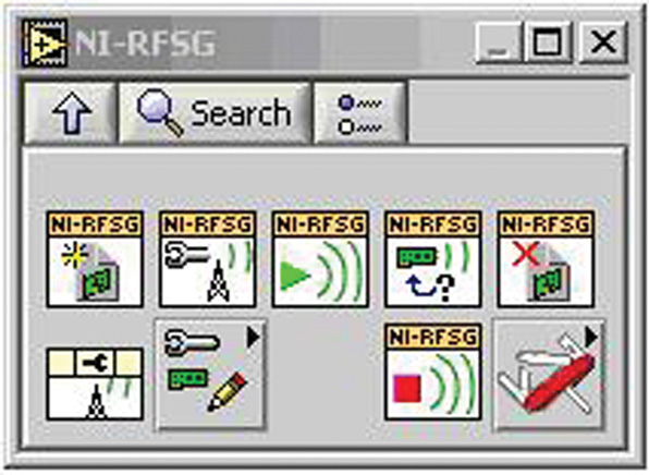
Generating the OFDM Signal with NI-RFSG
The complex baseband representation of the OFDM signal, obtained after filtering and up-sampling, can be used to generate a real OFDM signal using the NI-RFSG palette shown in Figure 11. The complex baseband signal can be written to the arbitrary waveform generator (ARB) memory, generated and up-converted using the NI-RFSG VIs.
Conclusion
OFDM is a modulation technique that is widely used for high speed data transfer. Because of this, many OFDM-based transmitters and receivers, with different designs and specifications, are being built. With LabVIEW and NI Modular instruments, these devices can be prototyped and tested quickly and easily. Also, LabVIEW provides the flexibility needed to quickly change a system design to test several different designs with very little effort.

Ashwin Prasad received his BS degree in communications and signal processing from the RV College of Engineering, Bengalore, India, in 2005. He is now a software engineer in the RF and communications group at National Instruments, India. He is currently working on means of improving the performance of communication algorithms on PCs, using commercially available technologies, including multi-core processors and stream processors, such as GPUs. His other interests include compilers, graph visualization and applied mathematics.