
 In the mid-1990s, the market clearly indicated a desire for more fully integrated waveguide related components and a development program to meet this need was begun. Credowan was in a strong position to offer key components in this development, particularly loop couplers and flexible waveguide. This article focuses on that development and particularly on the evolution of the 10-HW-9065 water dielectric load assembly and the associated product family used for testing high power radar transmitters.
Starting with loop couplers, they offer a small compact option for the monitoring of forward and reverse power and/or frequency. The relatively low specification directivity in such couplers and a relatively narrow bandwidth is not normally a hindrance compared to the cost-effective and robust long-term solution they provide for high power microwave testing in general, and the radar industry in particular.
Add to that flexible waveguide, which offers two substantial advantages. First, the positioning of waveguide components can be versatile at the S-band 3 GHz frequency with typically 3 to 5 mm of displacement in three dimensions being quite achievable. They also offer excellent survivability against applications where shock and vibration are key factors.
Power Handling
However, care must be taken to look at true power handling, as traditional flexible/ twistable waveguide has considerable limitations, especially in long-term use. Options of seamless waveguide have been developed to offer a significantly higher powered option. In the particular subsystem we are considering it was not necessary to have a flexible assembly, although commonly it is.
Other coupler options would include both broad-wall and cross guide, where perhaps higher directivity is required, or coupling values lower than the traditional 50 dB that radar dual couplers are designed for.
The core technology to the 10-HW-9065 is the novel and unique method of configuring a high power waveguide load utilizing water both as the absorber and the coolant. The use of water dielectric loads dates back as far as the 1960s, but these original designs incorporated glass water containment features, which were far from robust in application. A combination of glass, extremely hot water and mobile radar systems set an impossible challenge for engineers tasked with establishing real confidence and real high power test regimens.
Updated Technology
For the new unit this technology was updated by replacing the glass elements with Teflon elements. Similarly, the manufacture of a hollow precision cone to extremely accurate angular and surface finish specifications paved the way for a high performance device and also provided a water pressure differential of 10 Bar (1 MPa).
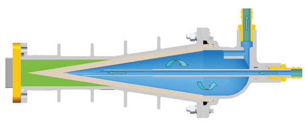
The basic principle of water dielectric loads (illustrated in Figure 1) is that a conical taper-shaped cavity is created for the high power microwave energy to enter, while a highly specialized waveguide window allows the RF energy to pass in a controlled way into a continuously recycling water heat sink.
In simple terms cold water is pumped into this cavity, which becomes heated by the microwave energy and is expelled. When used in controlled conditions for military applications, the water can be recycled and cooled through a chiller. On board ship, this may well be the ship’s chilled water supply.
The use of relatively low quality water is quite acceptable in most instances and coolant such as Glycol can be added to constitute up to 60 percent of the total fluid content. That is provided scaling and other contaminants are carefully monitored and the loads are cleaned and flushed through with suitable solvents after each sustained use. For systems where continuous water flow is used with no possibility of a maintenance period then cleaned and de-scaled water must be used.
Product Development

Taking these constraints into consideration the 10-HW-9065 was developed after a major customer approached the Credowan engineering team with a view to a complete subsystem, which is shown in Figure 2. The capabilities for this sub-system included the need to monitor both the power and frequency, which entered the load and for it to be configured on a number of different waveguide flange configurations. More of a challenge, though, was the requirement to use the load in two different orientations.
With the need to keep the coolant output at the highest point of the load itself and the cooling port configuration not being a field adjustable option and therefore remaining static, the waveguide input had to be variable. Also, the use of flexible/twistable waveguide was not an option because the power level of the system under test was too high. The use of seamless flexible (non-twistable) waveguide would overcome the power problem, but analyzing the amount of regular bending and the required bend radii to keep the overall unit as compact as possible would certainly mean regular replacement of the flexible section, making it not a cost-effective or reliable solution.
However, simply adding a rigid 90° bend in conjunction with the adjustable stand gives the orientations needed and by the addition of a 90° twist instead of the bend provides a third orientation if it were ever required.
Water dielectric loads are fundamentally extremely small for the equivalent power handling, and power levels of 20 kW+ average power are readily achievable at 3 GHz for S-band radar applications, determined primarily by the coolant flow rate, which is typically 10 litres per minute for a 16 kW rating. Also, if the specific heat and the flow rate of the coolant are known, the difference between the input and output temperature can provide a calorimetric measurement of the power.
Flow Monitoring
It is fundamental to the operation that the absorber taper is entirely full with water/coolant; not only for the power performance, but also because an air blockage or pocket could limit or stop the flow. It is recommended that all users of water cooling devices monitor the flow and ensure that there is no air in the system.
Therefore, two of the important factors in designing such a product are the back pressure of the cooling system and ensuring that the orientation with the flow output is always uppermost on the system. Peak powers can rise above a megawatt should the radar system require it, and the waveguide can typically handle a 3 Bar (300 kPa) pressure differential to achieve high power levels.
Keeping within these parameters, a fundamental design for the water dielectric load assembly was established, offering a robust subsystem, combining a standard dual-loop coupler, with a relatively standard water dielectric load. This was fitted into a robust and versatile frame including a series of waveguide flange adaptors to suit the range of requirements. The end application for this product is for the field testing of large mobile S-band radar transmitter systems, monitoring their power curves and ensuring frequency consistency.
Although geared towards S-band radar applications, it is also suitable for higher or lower frequency needs and designs within the product range including devices at 1.6 and 5.4 GHz, covering L-band and C-band radar applications.
Conclusion
In essence, this type of water dielectric load assembly is based on established technology that is proven to meet the strict and robust requirements of radar applications. One of the great attractions of this technology is that should the unit receive any kind of mechanical or systemic abuse, such as an interruption of water supply, while the failure may be catastrophic at the time, the repair cost will be minimum as the unit is designed for quick disassembly and refurbishment.
Credowan Ltd.,
Chichester, UK
+44 (0) 1243 670711, www.credowan.co.uk.
RS No. 303