
Basic Design Concept

A tunable filter with loss compensation can be constructed by cascading passive tunable filters (or tunable resonators), an RF gain block and external/internal equalizers, as shown in Figure 1. Here, the filtering parts are responsible for creating the needed frequency response, while the gain block compensates for the insertion losses. If the filters (resonators) are tunable (mechanically or electrically) their input/output impedance variations may be considerable, leading to variations of IL and BW within the tuning range. To avoid such an undesirable phenomenon, external and internal equalizing circuits must be added to improve the overall performance. The practical realization of a tunable filter with constant bandwidth and loss compensation (stabilization) requires performing the following basic steps:
• The design of tunable resonators from which the tunable filter is assembled. In this article, step-impedance varactor-tunable resonators will be employed to realize such filtering elements;
• The choice of a configuration of coupling (equalizing) elements providing stabilization of the bandwidth within a specified tuning range. If the filter consists of several resonators, both external and internal equalizers must be determined to provide the best stabilizing effect;
• The choice of the gain block and the design of equalizing elements to minimize the IL variation within the tuning range;
• Integrating all the components into a single assembly, in order to reach the goal: a bandpass varactor-tunable filter with constant IL and BW and loss compensation.
Step-impedance Varactor-tunable Resonators
Tunable resonators and filters can be realized through a number of methods.1–5 However, a step-impedance resonator (SIR) is an excellent candidate for creating microwave tunable filters due to some advantages:6
• Easy fabrication using planar technology;
• Reasonable manufacturing tolerances;
• Easy integration with varactors and other lumped or distributed components;
• Simple biasing circuitry;
• Wide-range tuning ability (up to 50 percent) with commercially available varactors.
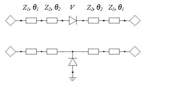
The symmetrical configuration of the SIR, shown in Figure 2, is considered below. It consists of the two lines with different impedances, Z1 and Z2 and electrical lengths θ1 and θ2, respectively. The varactor diode, used as a tuning element, is placed in the center of the resonator. A more detailed analysis of these configurations6 showed that the frequency tuning range and mode separation depend on the parameter ζ = θ1/(θ1 + θ2) as well as the type of coupling element at the input/output ports—capacitive or inductive.

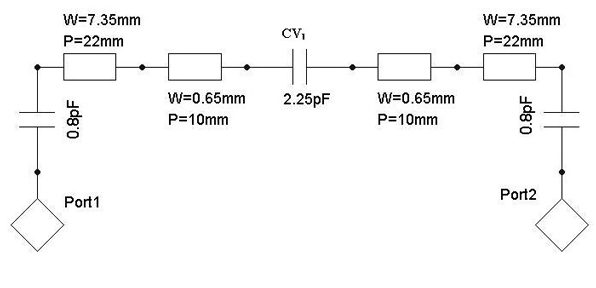
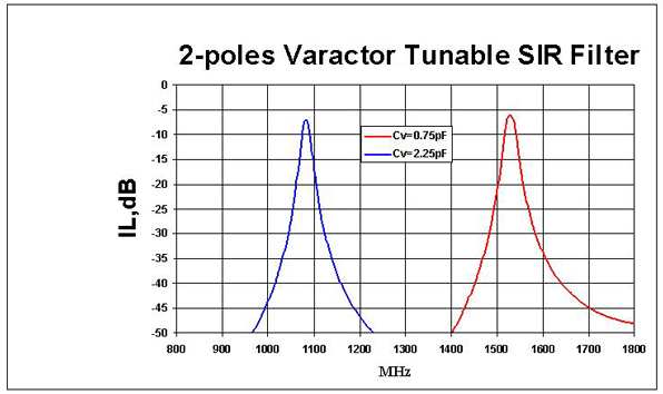
The best results are obtained for the parameter ζ = 0.7 to 0.8, assuming Z1 = 20 Ω and Z2 = 80 Ω. The SIR with a series varactor demonstrates a higher separation between the principal and nearest higher mode, while its counterpart, with a parallel varactor, has better tunability. Since both SIRs have a symmetry plane with respect to the varactor, only odd (or even) modes can be tuned while the others are fixed, depending on the position of the varactor-parallel or series. This effect reduces the frequency separation of the resonant modes. However, if the cut-off frequency of the gain block is chosen near the second harmonic, this parameter can be improved in principle. Consider, as an illustration, the varactor-tunable SIR with capacitive input/output couplings shown in Figure 3. The varactor (capacitor CV1 with Q = 100 at 1 GHz) is connected in series and its capacitance varies in the range 0.75 to 2.25 pF, depending on the applied bias voltage. The biasing circuitry is not shown for simplicity.

The SIR is assumed to be fabricated on a Duroid RO-3006 substrate: εr = 6.15, tanδ = 0.001, thickness H = 1.28 mm and a conductor thickness T = 0.035 mm. For these parameters, Z1 = 19.9 Ω, Z2 = 80 Ω, θ1 = 60° and θ2 = 24.3°, resulting in the parameter ζ = 0.71. The other schematic elements are indicated in the figure, assuming that the capacitors Q = 100. The IL was simulated using the Ansoft Designer SV-2.28 circuit simulator for two capacitances of the varactor CV1 = 0.75 and 2.25 pF (see Figure 4). The other characteristics of this tunable resonator are given in Table 1. It is clear that the variations of bandwidth and insertion loss are not acceptable and need the stabilization discussed below.
Stabilization of BW and IL
When it is necessary to stabilize BW and IL within a tuning range, the following factors should be taken into account:

• Frequency dispersion of the constitutive characteristics of the substrate, namely εr and tanδ;
• Frequency dispersion of the parameters of both lumped and distributed elements of the filter, responsible for its frequency performance;
• Frequency behavior of the coupling coefficients of the input/output and inter-resonator coupling elements.
The roles of these factors and their real contributions in degrading the filter performance depend on the operating frequency. However, in many practical situations, the coupling elements are the most essential factors leading to variations of BW and IL. A variety of equalizing circuits can be employed to stabilize BW, but only simple capacitive L and T configurations are considered, which can be easily integrated with planar technology.
Single-tunable Resonator

A single-tunable resonator with L-type equalizing circuits at the input/output ports is shown in Figure 5. Assuming that the transmission matrix ABCD of a tunable resonator |Tr| is known, the transmission matrix of the tunable resonator with equalizers |Tre| can be written as

where |Tein| and |Teout| are the transmission matrices of the input and output equalizers consisting of reactances Z1L and Z2L

After multiplying the matrices in Equation 1, the elements of |Tre| are determined as

where Ar, Br, Cr and Dr are elements of the transmission matrix of the tunable resonator.6 Assuming a symmetry with respect of the input and output ports results in Ar = Dr; q = Z1L/Z2L. By transforming the ABCD matrix into a scattering matrix,7 with a system impedance Z0, S21 can be written as

or
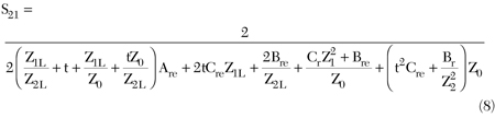
where t = 1 + q. The insertion loss expression, IL = –20 log|S21|, can now be used for optimizing the tunable filter’s frequency response within a specified tuning range. The equalizing reactances Z1L and Z2L are considered now as independent variables satisfying the two criteria:
a) minimum variation of insertion loss;
b) minimum variation of bandwidth.
To simplify the minimization procedure to reach the goal, the capacitive elements, Z1L = 1/j2πfC1L and Z2L = 1/j2πfC2L are tried, so that the following error function ER can be introduced
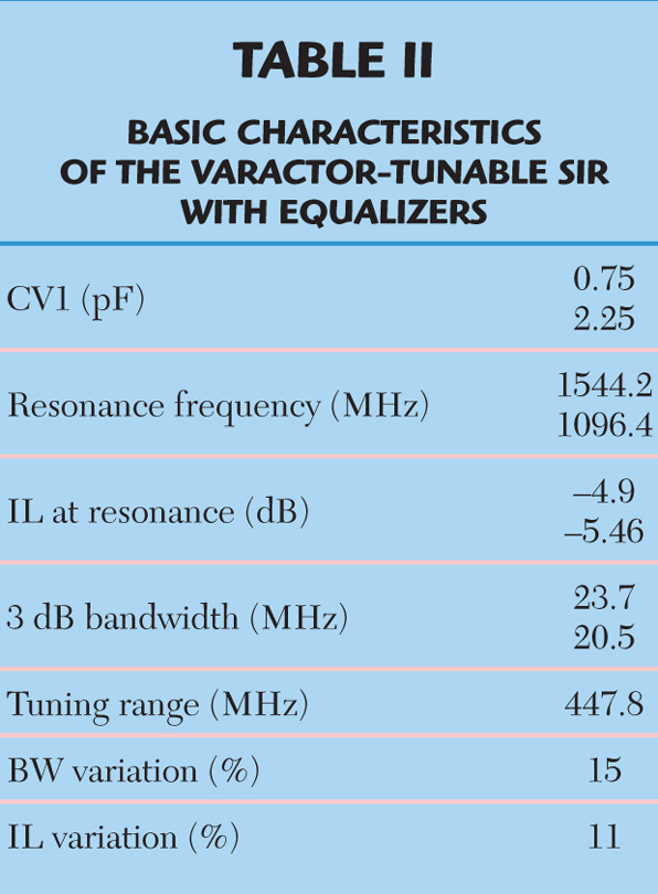
where t1 and t2 are weighting coefficients (t1 + t2 = 1) and V1 and V2 are the varactor biasing voltages corresponding to the specified tuning range of the resonator. A search for a minimum of the error function (the details are omitted due to space limitation) results in the value of the equalizing capacitors of CIL ≈ 2.2pF and C2L ≈ 1pF. The simulated frequency responses obtained for these equalizers are shown in Figure 6, with the same varactor’s capacitors values as before.
A comparison of both responses demonstrates that the stabilizations of IL and BW are successful, namely the BW variation is reduced by more than three times and the IL variation is reduced by approximately five times. Table 2 summarizes the results of the above optimization.
Coupled-tunable Resonators
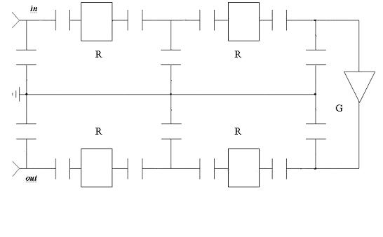
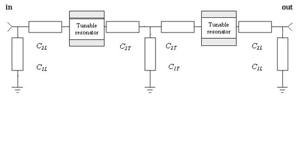
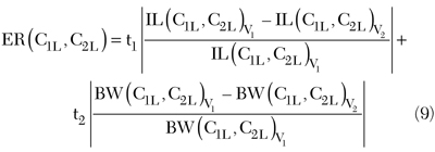
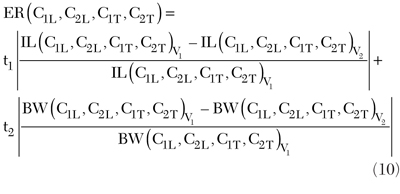
Coupled-tunable resonators, with a T-type capacitive equalizing circuit as an inter-coupling element, are shown in Figure 7. Assuming that the transmission matrix ABCD of a single-tunable resonator |Tr| is known, the transmission matrix of the coupled-tunable resonator with external and internal equalizers |Tre| can be written using the same approach as described above for the single-tunable resonator. However, the error function must now be modified to include the parameters of the inter-coupling elements of the T-equalizer, C1T and C2T. It can be written as
By optimizing the error function, the values of the equalizing capacitors have been determined to be
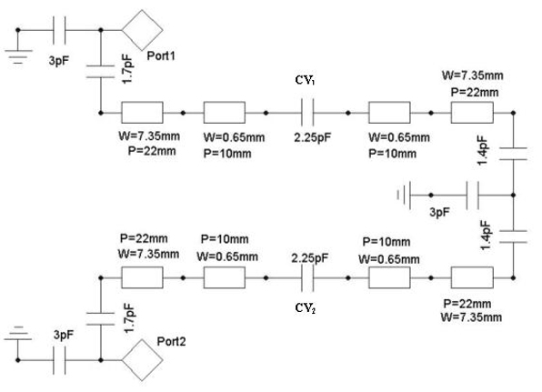
C1T = 3 pF, C2T = 1.4 pF, C1L = 3 pF and C2L = 1.7 pF
The schematic of the equalized two-pole filter is shown in Figure 8 and its simulated frequency responses are shown in Figure 9 for CV1 and CV2 varying in the range 0.75 to 2.25 pF. The BW varies from 18 to 22 MHz and the variation of IL is 6 to 7 dB, within the tuning range 1.08 to 1.53 GHz. However, this level of insertion loss is unacceptable for many applications. To compensate for the insertion losses, a gain block is added between the two-pole tunable filters, as shown in Figure 10. It should be pointed out that implementing the gain block may require a correction of its gain slope within the specified tuning range in order to obtain a flatter IL.
Fabrication and Testing
In order to verify the suggested concept and the results of the nonlinear optimization of the error functions (Equations 9 and 10), varactor-tunable filters were fabricated using planar microstrips on Duroid RO-3006 substrates, SMA connectors and the step-impedance topology previously described. Abrupt junction tuning varactors SMV1405 from Skyworks Solutions Inc. were employed with a biasing circuit providing 0 to 15 V.
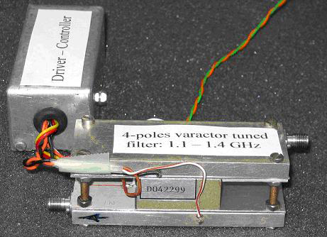
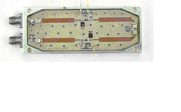
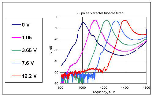
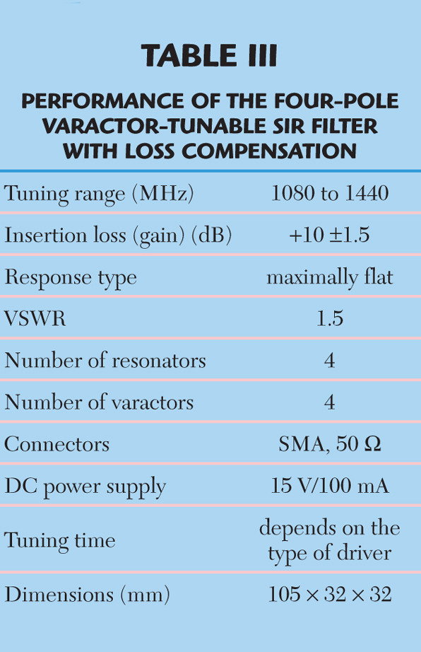
A photograph of the two-pole tunable filter is shown in Figure 11. The measured IL of this filter is shown in Figure 12. Its tuning range is from 1.0 to 1.4 GHz, its 3 dB BW = 60 ±5 MHz and its IL = 3.5 to 5.0 dB. A four-pole tunable filter has been assembled, using two identical two-pole tunable filters, with a gain block between them. The Mini-Circuits LNA-ZFL1000LN with a gain of approximately 20 dB was integrated within these filters for loss compensation. A photograph of the whole assembly is shown in Figure 13. A special controller-driver has been designed to distribute the biasing voltages between the four varactors from a single DC power supply. Figure 14 shows the measured IL for different biasing voltages. Table 3 summaries the performance of the fabricated four-pole tunable filter.
Conclusion
Varactor-tunable bandpass filters based on SIRs have been presented in this article.

The major limiting factors such as variation of BW and IL were overcome by using L- and T-types of equalizers. Almost constant BW and IL over the 40 percent tuning range have been achieved with varactor diodes available in the market today.
The filters are easy to fabricate using planar microstrip technology suitable for mass-production. n
Acknowledgments
The author would like to thank D. Vogel and M. Berger from EYAL Microwave (Israel) for supporting this work and helping to fabricate the varactor-tunable filters, and A. Shulsinger for designing the controller-driver used in the laboratory tests of these filters.
References
- I.C. Hunter and J.D. Rhodes, “Electrically Tunable Microwave Bandpass Filters,” IEEE Transactions on Microwave Theory and Techniques, Vol. 30, No. 9, September 1982, pp. 1354–1360.
- R.M. Kurzrok, “Tunable Combline Filter Using 60 Degree Resonators,”
Applied Microwave & Wireless, Vol. 12, November 2000, pp. 98–100.- A.R. Brown and G.M. Rebeiz, “A Varactor-tuned RF Filter,”
IEEE Transactions on Microwave Theory and Techniques, Vol. 48, No. 7, July 2000, pp. 1157–1160.- L.G. Maloratsky, “Assemble a Tunable L-band Preselector,”
Microwaves & RF, September 2003.- B. Kapilevich and R. Lukjanetz, “Modeling Varactor-tunable Microstrip Resonators for Wireless Applications,”
Applied Microwave & Wireless, Vol. 8, No. 9, September 1998, pp. 32–44.- D.M. Pozar,
Microwave Engineering, John Wiley & Sons Inc., Hoboken, NJ, 2005.- Ansoft Designer SV-2.2, www.ansoft.com.
 B. Kapilevich received his MS degree in radio-physics from Tomsk State University, Russia, in 1961, his PhD degree in microwaves from Novosibirsk Technical University, Russia, in 1969, and his Dr. Sc.Tech. degree in microwaves/antennas from Moscow Power University, Russia. From 1988 to 2001, he was a professor and head of the applied electromagnetics department of the Novosibirsk State University of Telecommunications, Russia. Since 2002, he has been a professor in the department of electrical and electronics engineering of The College of J&S, Israel, and head of the microwave-mm-wave group of the Israeli Center for Radiation Sources and Applications. His research interests include microwave and mm-wave devices, measurements and characterization of materials at high frequencies.