
Applied Wave Research Inc. (AWR™) has focused on an engineering effort to eliminate uncertainty in the high frequency design process by closing gaps in existing design methodologies and strengthening the links between system specifications and circuit performance, electrical design and physical layout, and computer simulation and RF measurements. This focus on "RF Closure" is part of the latest Microwave Office™ (MWO 2003) software, which includes a new time-domain simulation engine and features a dramatically improved harmonic balance simulator. The release also includes AWR's new TestWave™ module that integrates electronic design automation (EDA) with test and measurement equipment, and there are new electromagnetic (EM) simulation options as well. Collectively, the design suite is aimed at improving the product development process by reducing risk, improving simulation capabilities and closing the verification loop with links to test and measurement instruments.

New Time-domain and Frequency-domain Capabilities
The focus of any EDA solution is bounded by the limits of its simulation technology and this new version of Microwave Office is clearly aimed at pushing the limits to solve larger and more complex problems quickly and efficiently. The harmonic balance simulator has gone through dramatic changes to increase both capacity and simulation speed. Figure 1 depicts the magnitude of the improvements in simulation speed, where large designs (containing hundreds of elements) typically run over 500 times faster than previous versions of the design suite. The results are even more impressive when "tuning" on large nonlinear circuits with near real-time feedback on performance. A practical test case is a Gilbert Cell mixer containing nine bipolar transistors modeled with the veritable Gummel Poon model. For an RF power sweep, the simulation time was reduced from over 17 seconds with the previous release to just under two seconds using Microwave Office 2003 software. The speed and capacity improvements can also open up designs to more rigorous statistical modeling and yield analysis, which now becomes practical on circuits that may have consumed too much simulation time in the past. The Microwave Office 2003 harmonic balance simulator performs 10 to 1000 times faster for most problems and can handle significantly larger problems than last year's version.
While frequency-domain techniques remain the mainstay for most RF/microwave design, time-domain simulation can provide an important complement and can solve unique problems such as those found in phase-locked loops or oscillators during start-up conditions. Microwave Office 2003 is the first version to include an optional time-domain engine to augment the harmonic balance, Volterra and EM simulators. The time-domain engine in MWO 2003 software is much more than just another SPICE simulator: AWR has integrated Synopsys' HSPICE® simulation engine because it is truly the "golden standard" for accurate time-domain simulations and is also the "sign-off" standard at most commercial integrated circuit (IC) foundries. While integrating HSPICE with AWR's core technology, a great deal of focus was placed on developing models, libraries and measurements, completely compatible and seamless, between frequency and time-domain engines. One advantage in using HSPICE within the MWO 2003 environment is that the extensive library of transmission line elements and discontinuities have been mapped into equivalent time-domain representations. EM structures and S-parameters can be incorporated in addition to all the standard SPICE elements.

Simulation and Measurement
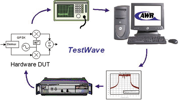
The new TestWave module provides a comprehensive integration of simulation with test and measurement solutions from a variety of suppliers. TestWave software enables designers to combine computer simulations with actual hardware test and measurement into one experiment. For example, the TestWave product can be used to collect modulated signals such as 802.11g or 3GPP from AWR's Visual System Simulator™ (VSS) product and feed them directly into an IQ signal generator that may be connected to an actual transceiver (see Figure 2 ). A major advantage of this integration is that designers can take into account "real world" effects that may be overlooked in a pure simulation environment. VSS can process and download arbitrary modulated signals to an IQ signal generator (for example a Rohde & Schwarz AMIQ/SMIQ or Agilent ESG-D) and the signals can be used directly in hardware measurements. Similarly, the measured data from a spectrum analyzer or vector signal analyzer can be shared automatically with the simulation software, used as a block in a system simulation. This ability forms a complete design process loop of simulation, signal generation, measurement and simulation, as shown in Figure 3 . It is also possible to share data masks and ideal waveforms between test and measurement equipment and VSS software, based on wherever desired waveforms are most readily available. In addition, imported IQ waveforms can be used as a stimulus to drive simulations.
The TestWave module supports a wide variety of test equipment, including suppliers such as Anritsu, Rohde & Schwarz, Marconi Instruments, Fluke/Philips, Tektronix, Boonton, LeCroy, Yokogawa, IFR, Wandel & Goltermann, Advantest and HP/Agilent. Equipment types supported include today's most advanced vector signal generators and vector signal analyzers as well as more conventional network analyzers, spectrum analyzers and oscilloscopes. TestWave software can easily import data from a network analyzer, oscilloscope or spectrum analyzer.
The TestWave test and measurement integration works from within the AWR design environment. The test and measurement equipment appear as part of the simulation project tree that shows the systems, schematics, data and graphs in a clearly visible Windows format. System blocks that connect to IQ test equipment can be placed directly into a schematic. It is even possible to perform mathematical functions on signal traces, such as addition, subtraction, impedance renormalization and stability calculations. The TestWave integration utilizes the advanced Microwave Office application program interface (API) to facilitate virtual "plug-in" applications. The integration supports a variety of connectivity methods between computer hardware, and test and measurement gear, including RS-232, GPIB and LAN interfaces.
Electrical and Physical Domains
Another large gap in the product development process remains between the electrical and physical domains. Even though most integrated design suites include EM simulation as part of the solution, many 3D challenges drive users to non-integrated solutions to analyze physical effects. In the case of MWO 2003 software, an integrated 3D planar method-of-moments (MoM) EM solver is built into it, but many companies also rely on additional EM point tools for full 3D analysis or complete MMIC simulations. It remains a fact today that no single EM simulation technique can address all the problems microwave engineers face.
To provide the best of all possible solutions, AWR worked with leading EM simulation companies to create the EM-Socket™ interface. This open standard leverages the Microwave Office API to facilitate greater flexibility and accommodate a variety of design methodologies. The EM-Socket product was developed to interface to virtually any EM simulator and to seamlessly integrate into the Microwave Office design flow. With the EM-Socket software, users can capture a physical structure once (using the Microwave Office GUI) and then send the analysis out to multiple EM tools to compare results. Users can also launch the native capture program for the specific EM simulator. This enables users to combine various EM algorithms, such as finite element analysis, FDTD, and a variety of MoM approaches to solve planar and full 3D problems.
Sonnet Software's EM product is among the first products available through the EM-Socket interface. Sonnet complements AWR by providing a robust fast frequency sweep, as well as supporting a variety of basis functions that enable representations of structures that do not correspond well to a rectangular grid. An interface is also available to Zeland Software's IE3D product. IE3D uses MoM techniques in a non-gridded solver and can handle much more arbitrary 3D structures. For full 3D analysis, AWR is supporting the Analyst™ product from Simulation Technology and Applied Research (STAR). More information on the integrated products is available from the individual suppliers. Additional EM simulators from other suppliers will be available through the EM-Socket software in the future.
New Subsystem Analysis (Budget) and Behavioral Models
MWO 2003 software includes a new budget analysis capability, and a variety of new and improved behavioral models. The existing amplifier and mixer models in the circuit simulator have been significantly extended. The amplifier model now supports full noise and S-parameter characterization, and the accuracy of its compression model has been improved. The mixer model also includes the characterization of all port-to-port isolations, noise and distortion effects. VSS behavioral models have also been extended and the software now uses a seventh-degree model for a nonlinear amplifier, which includes noise as well. The mixer can be characterized either by a spur table or by an estimate of the spur levels based on the switching-function analysis of Gardiner and Yousif.1
Conclusion
For 2003 the entire Microwave Office product line has been refined, improved and extended to handle higher complexity designs. Every component in the software, from the simulation engines to the layout editor, to the schematic interface, has been painstakingly optimized to provide higher performance. In addition to the simulation improvements, the schematic and layout editors are both over 10´ faster at displaying information. This will provide MMIC/RFIC designers the ability to layout complete reticles and wafers without the need for the expensive dedicated IC layout tools that are commonly used for digital IC design. The new release, available in Q2 2003, includes comprehensive upgrades to the Microwave Office design suite as well as the new TestWave product that integrates test and measurement equipment with the software simulation suites.
Reference
1. J.G. Gardiner and A.M. Yousif, "Distortion Performance of Single-balanced Diode Modulators," Proceedings of the IEE , Vol. 117, No. 8, 1970, p. 1609.
Applied Wave Research Inc. (AWR), El Segundo, CA (310) 726-3000, www.appwave.com. Circle No. 302