
COVER FEATURE
Exploring a Three-dimensional Universe
CST of America Inc.
Wellesley, MA
Engineers are branching out. Gone are the days when 3D electromagnetic fields belonged to the specialized domain of antenna and cavity filter designers. Today's higher frequencies and the compact nature of designs are forcing engineers to take wave propagation and stray field effects into account in calculations which would previously have been carried out in circuit simulators.
CST MICROWAVE STUDIO (CST MWS), now available in version 3, is a cutting edge three-dimensional electromagnetic field simulation software package that features an intuitive user interface and powerful geometrical modeling capabilities, together with fully parameterized input, optimization and a multitude of additional features, which promote straight forward design and reduced time-to-market. This article provides an extensive introduction to CST MWS and its new features.
FOUNDATIONS
CST MWS is based on the finite integration method (FI), a one-to-one translation of Maxwell's Equations, into a discrete space formulation without simplification or specialization. Consequently, it is a general approach, applicable to all electromagnetic, as well as other physical phenomenon. The FI method originated from the needs of particle accelerator designers, and through its continuous application to new challenges, its theoretical foundation has been developed dynamically over more than 25 years. It is characterized by maintaining the physical properties of electromagnetic fields on a grid space, inforcing the conservation of energy, for example. In turn, the user benefits from a robust tool that guarantees physical solutions.
The FI method is formulated on a structured, but not necessarily orthogonal, grid. Although similarities can be found with finite difference (FD) methods, it should be noted that the FI method's fundamental approach is unique.
USING CST MWS -- AN EASY TASK
On opening CST MWS, an intuitive Windows-based graphical user interface (GUI) appears, which provides the user with all the information necessary during the simulation process. The integration with the Windows environment facilitates the beginner's start into 3D electromagnetic field computation with its well-known look and feel, as demonstrated in the 3D current distribution example shown in Figure 1.

MODELING THE STRUCTURE
The integrated three-dimensional structure modeler is based on the ACIS kernel version 6.2, embedding the graphical capabilities into exceptionally easy-to-use features. Complicated 3D structures can be effortlessly created from primitive shapes via mouse input by using a choice of "pick" operations, backed up by Boolean operations and transformations on single primitives. Chamfer and blend operations facilitate the technical design of structures. Additional features include the extrusion of arbitrary 2D profiles along arbitrary paths.
Moreover, the geometry does not have to be modeled inside CST MWS. Powerful import and export options in both 2D (GERBER, DXF, GDSII) and 3D formats (SAT, IGES, STEP, STL) mean that CST MWS can be fully integrated in an existing CAD environment. Furthermore, the CAD import process is fully supported by numerous sophisticated and automatic shape healing tools.
Modern Meshing Techniques
A structured orthogonal grid enables a fine sampling of the geometry and electromagnetic fields while retaining minimal memory requirements. Simulations using several million mesh points are easily performed. This efficient organization of information enables the fast broadband calculation in the time domain.
The meshing process itself is performed by an expert system, which only needs three basic pieces of information in order to create an accurate representation of the studied structure, that is, the spatial sampling rate of the electromagnetic wave, the sampling rate of the geometry and the maximum allowable inhomogeneity of the grid. Using default parameters will provide excellent results.
Although the user can easily influence the grid in order to get better grid resolutions on strategically important regions, an adaptive mesh refinement is implemented that automatically generates high precision solutions.
Advanced Material Representation -- THIN SHEET
Conventional wisdom often claims poor structure approximation to be a major disadvantage of FD (like) methods. The company's unique PERFECT BOUNDARY APPROXIMATION technique (PBA) changes all of this, enabling excellent solutions even with comparatively coarse grids. PBA allows the modeling of arbitrary curved surfaces, thus reducing the need for finer meshing and eliminating all staircase approximation errors. PBA also takes into account the thickness of metallic sheets or strip lines within one grid cell, without explicitly meshing it. The consideration of field singularities of electromagnetic fields on edges additionally reduces the number of mesh points necessary to reach a precise field and impedance computation.
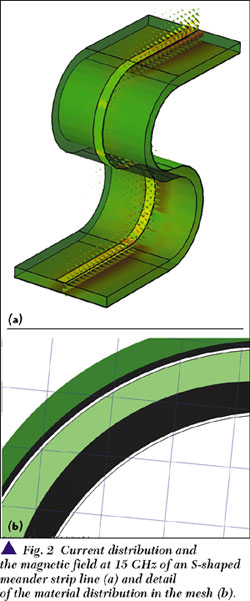
PBA provides a highly accurate representation of fine metallic layers oriented along grid planes. The breakthrough provided by the new THIN SHEET technique (TST), an innovative development based on PBA, is the representation of arbitrarily shaped and located thin metallic layers, which significantly reduces the number of mesh points necessary. Figure 2 demonstrates the modeling of a 10 µm thick meander strip line by using TST. PBA takes into consideration the exact curvature. The conductor lines (10 µm thick) cut mesh cells, but with TST the fields still can be calculated exactly. This new technique will be available to users soon.
WORKING IN THE TIME DOMAIN
The FI method's most powerful weapon is the explicit time domain calculation of electromagnetic fields. A broadband simulation can be performed in just one solver run, quickly and accurately detecting the system response including all resonances. Losses can be included firstly by means of a loss tangent or conductivity of a dielectric material, or secondly, for good conductors, by a surface impedance model.
Advanced material characteristics such as frequency dependent, gyro-electric and gyro-magnetic materials will be available with the next version of CST MWS.
Feeding the Input Power
In order to start the time domain calculation, one of the following three types of power sources has to be defined: a plane wave incident, a current source (which can be arbitrarily located inside the calculation domain) or a waveguide port. If the last is used for multi-conductor waveguides, like coplanar lines, the new multi-pin port feature enables an arbitrary current allocation.
By default, the excitation signal will be a sinus-modulated Gaussian signal, but users are free to define their own excitation functions. Rectangular pulses allow true digital simulations as well as time domain reflectrometry (TDR).
Scattering Parameters
The primary results are the generalized scattering parameters (S-parameters) for an arbitrary number of modes at each port. De-embedding of S-parameters allows both the modeling of the measurement environment as well as the reduction of the 3D field simulation to the electromagnetically important part of the structure.
S-parameters can be accessed via several viewing options and exported into Touchstone format for use in circuit simulators. Moreover, CST DESIGN STUDIO (CST DS), the company's latest development, can easily combine results from CST MWS. It is able to take into account higher mode coupling between parts of the structure, and thus derive the system behavior from structural parts simulated in 3D, enriched by additional analytical models or results provided by other tools.
CST MWS features a SPICE network parameter extractor from which a broadband, cascaded SPICE model, including losses, is created. The quality of the model is cross-checked by CST MWS.
3D Electromagnetic Fields
During the solver run, electromagnetic field patterns and far fields for an arbitrary number of frequencies can be monitored. Animations of electric and magnetic fields, surface currents and power flow grant insight into the device's functionality. Due to the plane wave excitation, radar cross section (RCS) computation is now available. Specific absorption rate (SAR) calculations, shown in Figure 3, is especially valuable in combination with the human data set. Taking into consideration the specific density and electric properties of different tissues like skin, bone and brain, for example, the SAR distribution can be calculated.

The memory efficiency of the FI method enables the simulation of structures that are large in comparison to the operational wave length, in particular farfield and RCS calculations. The challenge of representing small details on PCBs is met by the combination of the PBA with the FI method's innate ability to cope with large grid point numbers. Besides EMC considerations, new areas of application are being opened up, for example photonic band gap structures (PBG) and frequency selective surfaces.
Performance
It is the magnitude of applicability that makes CST MWS such a powerful engineering tool. Its efficiency has been demonstrated in various benchmarks, the latest of which was presented by Microwave Engineering Europe in November 2000. Some of the best known software providers joined in the examination of a Vivaldi antenna, as shown in Figure 4. CST MWS produced precise answers in a wide frequency range, underlining the superiority of time domain methods over frequency domain approaches in terms of memory and time expenditure. Calculation time for a broadband excitation from DC up to 10 GHz was 15 minutes, over nine times faster and about eight times more memory efficient, than commercial FE codes.

Highly Resonant Structures
The advantages of calculating nonresonant structures in the time domain are quite obvious. For the treatment of highly resonant structures additional tools have been designed to augment the simulation possibilities. An automatic auto-regressive (AR) filter determines frequency and quality factors of the resonances and predicts the future course of the signal. If the filter fulfills several quality criteria the time domain simulation stops. The accompanying reduction in simulation time can be tremendous. The AR filter may also be applied in a post-processing step.
Alternatively the structure can be broken down to nonresonant parts that can be recombined in CST Design Studio, where evanescent mode coupling is taken into account.
Supplements to the Time Domain
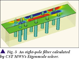
CST MWS additionally features an Eigenmode solver for cavity filter structures. A modal analysis algorithm determines the broadband S-parameters from the eigenmodes. The field pattern of one of the modes through an eight-pole filter is shown in Figure 5 in a cross section of the filter. Additionally, CST MWS also possesses an incorporated frequency domain solver.
DESIGNING WITH CST MWS
CST MWS assists in designing new devices in many respects, and in particular through parameterization, optimization and automation.
A fully parametric input allows the easy incorporation and improvements in a design. A structure constructed interactively using the powerful CAD interface can easily be parameterized at any time. Parameter studies are supported by automatic parameter sweeps. The results are summarized in comprehensive view graphs.
In addition, CST MWS features automatic optimization, allowing the user to freely define the goal function for multiple parameters. Parameterization and optimization are included in the CST MWS standard installation.
Integration into Work Flow
CST MWS utilizes Visual Basic for Applications (VBA) as its command language. VBA permits users to customize CST MWS to their own needs. Dialogue boxes may be created, data exported or additional results derived, which can again be visualized. A large number of settings and results are accessible through the VBA interface.
Using VBA language, CST is able to quickly respond to customer's requirements by providing macros for the derivation of secondary results from field calculations. Examples include the evaluation of TDR simulations, the creation of animations and reports and so on.
The consistent compliance with Windows standards permits access to CST MWS via OLE automation. The user can control CST MWS from Excel, for example, by setting parameters, starting the computation, querying, evaluating and visualizing the results.
CONCLUSION
The total value of owning CST MWS should be analyzed not only through its speed, accuracy and ability to evaluate large structures with a variety of solvers, but also in the light of its easy-to-use interface and powerful geometric modeling. The seamless integration into the Windows environment, including the VBA scripting language, OLE automation and the large variety of built-in features, such as CAD import options, makes it enormously valuable to engineers. Time to market can be reduced significantly, and the need for hardware prototyping virtually eliminated. Last but not least the product support team continues to offer informed and practical advice. Additional information is available on the web at www.cst-america.com or via e-mail at info@cst-america.com.
CST of America Inc.,
Wellesley, MA (781) 416-2782.
Circle No. 300