
TECHNICAL FEATURE
Complex Coaxial-waveguide Transitions at Millimeter-waves
Millimeter-waves have been used in commercial applications during the last decade as a result of the growing development of microwave multipoint distribution systems, local multipoint distribution systems, and digital audio and video broadcasting. In spite of many proposed simulation methods, experimentation remains a powerful tool to explore complex circuits and constructions. This article describes two types of coaxial-waveguide transitions that have been investigated experimentally over a wide frequency range at millimeter-waves. The frequency dependence of the equivalent circuit parameters has been obtained for different geometrical dimensions to facilitate the design of oscillators, amplifiers, mixers and converters.
Oleksandr Gorbachov
and Leonid Kasatkin
Gatax Technology Co.
Taipei, Taiwan
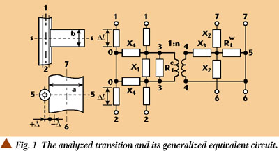
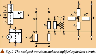
C oaxial-waveguide transitions are frequently used for different types of diode oscillators, amplifiers and mixers, especially at millimeter-waves. Equivalent circuits have been developed theoretically and experimentally by many authors for single-diode constructions where a coaxial line is placed close to a waveguide axis.13 For such transitions, the electromagnetic field symmetry allows the use of a quasi-static approximation of the current distribution through a coaxial line or more sophisticated methods to reach correct results for different geometrical dimensions over a wide frequency range. However, for multi-diode systems such as power combiners,4 voltage-controlled oscillators,5 active frequency up and downconverters,6 amplitude modulators7 or single diode systems (such as amplitude detectors,8 efficient wide-band injection-locked oscillators and amplifiers),9 the coaxial lines must be placed close to the lateral walls of a waveguide. In this case, the field asymmetry and sharp edges for a current flow complicate theoretical approaches to such transition simulation. For the first time, the theoretical analysis of a coaxial-line transition to a rectangular waveguide through a small hole has been carried out.1 The previously mentioned applications require a stronger coupling between coaxial and waveguide lines. Currently, to the authors' knowledge, only an approximate theoretical analysis exists for such transitions10 and they require an experimental verification. Most experimental works dedicated to transitions use simplified or generalized equivalent circuits and cannot produce the full set of parameters required for the design of many active and passive circuits of varying geometrical dimensions over a wide frequency band. In this article, the equivalent circuits and their parameters are defined experimentally for different constructions on the basis of a previous developed method.11 The analyzed transition and its generalized equivalent circuit is shown in Figure 1. Figure 2 displays a simplified equivalent circuit.
|
|
EQUIVALENT CIRCUITS
AND THE MEASUREMENT METHOD
The coaxial line axis shift by ±Δ for the transition's construction results in an impedance variation for the active device installed in the coaxial line and transformed to the waveguide. The essential and sufficient set of parameters is selected for each construction on the basis of measurements. The reference planes for the generalized case have been chosen in the following manner: The port 5-5 is placed in the plane perpendicular to the waveguide's axis and passed through the coaxial line axis. The positioning of the ports 4-4, 6-6 and 7-7 physically coincides with the reference plane 5-5. The ports 0-3 are disposed in the middle plane of the waveguide, parallel to its wide wall and perpendicular to the coaxial line axis (reference plane S-S). The equivalent circuit ports 1-1 and 2-2 are positioned physically in the same reference plane S-S. The coaxial line segments Δl determine the reference plane shift in accordance with experiments. The analysis shows that the reference plane shift Δl may be replaced by the reactive two-port element X4 and vice versa. The losses are shown as  and
and  relating to losses in coaxial and waveguide lines, respectively. The generalized equivalent circuit is valid if the coaxial line loads in ports 1-1 and 2-2 are positioned physically far enough from the upper and bottom walls of the waveguide. An investigation of the equivalent circuit parameters is carried out on the basis of two sets of measurements.11
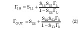
In the first set of measurements, a matched coaxial load Z0c is connected to port 2-2 and port 1-1 is connected to a variable reactance  represented by a coaxial sliding short or an open line structure. Port 6-6 is loaded by a waveguide sliding short and the phase and modulus of the reflection coefficients at port 7-7 of the waveguide are measured.
In the second set of measurements, ports 1-1 and 2-2 are loaded by matched impedances and ports 6-6 and 7-7 are terminated, as shown in the first set of measurements.
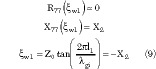
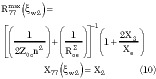
In the first set of measurements, at a fixed frequency fi , the port 1-1 reactance variation within the limits of = ± results in a measured impedance at port 7-7 represented by circles in the complex plane R, jX (either in rectangular or polar coordinates). In this case, the positioning of the waveguide sliding short corresponds to a distance of (2n + 1)
 /4 from the port 5-5, where g is the waveguide wavelength for TE01 mode and n is an integer. As a result, the circle center coordinates and radius are
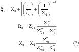
The term  = [(1/R1 w ) + (1/n2 )]1 is the total loss at port 4-4 with R1 w >> X3 (this correlation is usually valid).
The extreme values of the real and imaginary components for this circle are
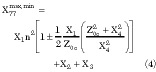
These extreme values are reached for the following reactance in the coaxial line
1 = X4 for R77 = 
2 = X1 for R77 =  (5)
(5)
3 = Rc X1 for X77 = 
4 = Rc X1 for X77 =  (6)
(6)
Here
At i = 1 and i = 2 :
X1 77 = X2 77  n2 X1 + X2 + X3 (8)
It is obvious that these extreme values of X77 are equal to the imaginary part of the circle center in Equation 1.
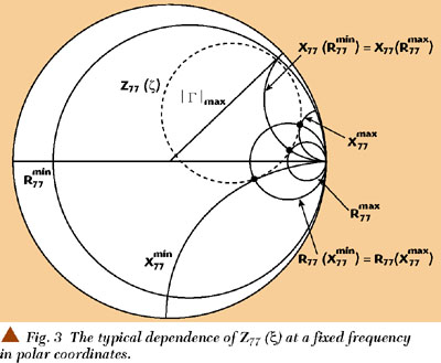
The term i = Z0c tan(2 l/ ) represents the reactance for the sliding short in the coaxial line or i = Z0c /tan(2 l/ + Δx ) for the open line structure. The variable l is the physical length between the coaxial short or open and the center plane S-S. The term Δx relates to the open line capacitance12 and is the wavelength in a coaxial line for the TEM mode. The typical dependence of Z77 ( ) for a fixed frequency is presented in Figure 3 in polar coordinates.
|
|
In the second set of measurements, for the same fixed frequencies fi , the shift of the waveguide short results in an impedance circle measured at port 7-7 where the minimal value of the impedance is
( gi is the wavelength in a waveguide and Z0 is its characteristic impedance for H10 wave mode):
The variable l1 is the physical length between the short position and the reference plane 5-5.
The maximum value of the impedance is
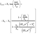
where
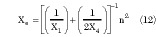
Equations 1 through 12 determine the full set of parameters for the equivalent circuit considered, and unknown parameters can be defined from the measured coordinates of the extreme points in the impedance circles Z77 ( ). Thus, for the first set of measurements, the reactance X4 is determined by tuning the coaxial line sliding short to the maximum value of the reflection coefficient in the waveguide (Equation 5). The value X2 is defined by tuning the waveguide sliding short to the maximum value of the reflection coefficient for the second set of measurements (Equation 9) that corresponds to the near-to-zero real part of an impedance and is limited by waveguide losses. In most cases X3 /Xe << 1, X2 /Z0 << 1 and X1 , n may be easily determined by the minimum mismatch in the waveguide (X1 is defined by Equation 5 and n by Equation 8). In a more complicated situation, X1 is determined by Equation 6 and X3 and n are defined by Equation 10. It is seen that the impedance circle center coordinates and its radius (in rectangular coordinates) for the first set of measurements give an additional possibility to verify the results.
The transition presented in the simplified equivalent circuit is attractive because of the possibility of a simple tuning of the transformation coefficient over wide limits by moving the short pedestal position . The equivalent circuit is a simplified version of the generalized circuit. The segment l represents the reference plane shift in the coaxial line relative to the center plane S-S in accordance with the movement of the pedestal position . The equivalent circuit ports 1-1 and 2-2 are positioned physically in the same reference plane
S-S. The positioning of other ports is similar to the one for the generalized equivalent circuit. The measurement methods are also the same. An active device such as diode may be installed either inside a coaxial section or directly on a pedestal. In the latter case, the equivalent circuit becomes more complicated than presented in the diagram due to the close positioning of different discontinuities in a transition area. Nevertheless, a wide tuning range for the transformation coefficient n has been successfully used in many real constructions.69,11 Providing a movable pedestal with a screw mechanism allows fine tuning for different circuits to properly match the active device and waveguide impedance, improving the yield.
MEASUREMENT RESULTS
Measurements were carried out for a rectangular copper waveguide with dimensions a = 7.2 mm and b = 3.4 mm. Results for the generalized case for the transition are presented in Figure 4. It is observed that a change in the outer diameter of the coaxial line and a shift in its axis relative to the lateral wall of a waveguide result in a wide variation of the transformation coefficient value. The dependence X1 (a/ ) has a parallel resonant character when the coaxial line axis coincides with the lateral wall of the waveguide with a resonant frequency around 31 GHz. Moreover, this resonance has a reverse frequency dependence that partially coincides with the theoretical results published by Lewin2 when the coaxial line is placed near the waveguide axis (so called "negative" inductance). However, moving the coaxial line position from the inside of the waveguide area (case 4 for Δ/a = 0.094) to its lateral wall (case 3 for Δ/a = +0.09) changes the sign of the reactive element X1 from positive to negative for the whole frequency range considered. For the position of the coaxial line axis where Δ/a = 0 and for a fixed value of its characteristic impedance, decreasing its outer (and inner) diameter results in an increase of the transformation coefficient n and the reactance X1 value (compare cases 1 and 2). The measured data have an important consequence to the design when one must choose matching conditions and consider bandwidth characteristics for different devices. In equivalent circuits where Δ >= 0, X3 << Z0 and the value X3 can be neglected. At Δ < 0 the value X3 cannot be neglected. For this particular case, the plot shows the value x3 for Δ/a = 0.094. For the transitions in both cases X4 /Z0 > 810 and X2 /Z0 < 0.12 for the frequency band considered, thus the values X4 and X2 may also be neglected for many applications.
|
|
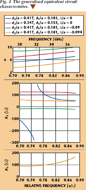
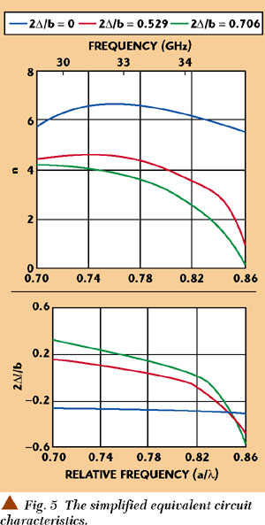
Figure 5 presents the dependence n(a/ ) and l(a/ ) for the simplified equivalent circuit at three different fixed positions of the short pedestal Δ. A very wide tuning range of the transformation coefficient can be observed, especially at higher frequencies. Just moving the pedestal position from the center plane S-S to the point of 2Δ/b = 0.706 results in varying the transformation coefficient n from 1 to 6 (from which the transformed value of any impedance from the coaxial line to the waveguide changes from 1 to 36 times). Note also that at the same time the reference plane shift is minimal, resulting in a wide frequency band of operation for many types of devices.
|
|
Therefore, choosing a coaxial line dimensions and its axis position relative to a waveguide lateral wall and utilizing the short pedestal positioning in the transition area allows the development of different kinds of easily tuned wideband devices and circuits. In this case, it is not necessary to use any additional waveguide iris (usually used) to match the active device impedance with a waveguide load. This also facilitates the frequency bandwidth requirements and increases the circuit efficiency. The active device impedance transformation through the variable coaxial line length even with some coaxial transformers cannot be used in many cases because, for the final result, it is important to not only have an impedance match, but the amplitude, phase and frequency dependence as well.
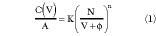
The total loss resistance has been measured for a rectangular waveguide power combiner with a number of N coaxial lines disposed at a distance of g /2 from each other along the waveguide axis (a = 7.2 mm and b = 3.4 mm). Each coaxial line was loaded by a matched resistance on one side and by an open line on the other. The distance from the open line edge to the reference plane has been chosen to get the maximum reflection coefficient in a waveguide (see Equation 7). The dependence (N) is close to (1/  ) confirming the fact that the losses have a statistical nature depending on the current flow. Remember that at the same time, the "useful" loads from the coaxial lines are summed in parallel in a waveguide as Z/N (in-phase current flow) resulting in a higher efficiency for multi-diode power combiners than for the single-diode constructions under the same other conditions. For a copper waveguide, 15 to 25 kΩ depending on the surface quality. Note that this result has been obtained without any iris at the waveguide output. Using an iris (especially the capacitance type) decreases this value significantly.
CONCLUSION
The measurement method presented allows the parameters of complex coaxial-waveguide transitions to be determined where a theoretical analysis is very difficult. The frequency and dimension dependence obtained for several constructions may be helpful to the design of different kinds of devices and circuits. *
References
1. N. Marcuvitz, Waveguide Handbook, McGraw-Hill, New York, 1951.
2. L. Lewin, Theory of Waveguides, Techniques for the Solution of Waveguide Problems, Butterworth and Co. Ltd., London, 1975.
3. R.L. Eisenhart and P.J. Khan, "Retrospective on the 1999 Microwave Pioneer Award," IEEE MTT Symposium Digest, 1999, Anaheim, CA, Vol. 4, pp. 16171620.
4. K. Kurokawa and F. Magalhaes, "An X-band 10-watt Multiple IMPATT Oscillator," IEEE Proceedings, 1971, Vol. 59, pp. 102103.
5. O. Gorbachov and L. Kasatkin, "Varactor-compensating the Characteristic Alterations for IMPATT Oscillators," Proceedings of 11th Microwave Electronics Conference, Vol. 2, 1986, Ordjonikidze (Russia), p. 76.
6. O. Gorbachov, N. Karushkin, L. Kasatkin, V. Satskov and S. Homenko, "Transmit-receive Module for 8-mm Radar with Pulse-to-pulse Switching of Operating Frequencies," Proceedings of 2nd Crimean Conference -- Microwave Technology and Satellite Reception, 1992, Sevastopol (Ukraine), pp. 8388.
7. "Investigating the Solid State Active Elements in Special Conditions and Creation of a Pulsed Transmitter," Research Report, Institute of Radio-electronics, Kazan (Russia), 1989.
8. "Creating the High Stable Pulsed Millimeter-wave Arrangement for the Electron-spin Spectroscopy," Research Report, Kazan State University, Kazan (Russia), 1996.
9. O. Gorbachov, "High Power Wideband Pulsed Millimeter-wave IMPATT Oscillators in Injection-locked Mode," Proceedings of the Institute of Radio-physics and Electronics, Vol. 34, 1989, Kharkov (Ukraine), pp. 3744.
10. A. Fialkovsky and A. Bondarenko, "The Cross Junction of the Coaxial and Rectangular Waveguides Through the Lateral Wall Slot," Electronics Technology, Ser. 1, High Frequency Electronics, Vol. 2, Moscow, 1988, pp. 3843.
11. O. Gorbachov and L. Kasatkin, "The Equivalent Circuit for Microwave Solid State Power Combiner," Electronics Technology, Ser. 1, High Frequency Electronics, Vol. 9, Moscow, 1989, pp. 5055.
12. E.W. Risley, "Discontinuity Capacitance of a Coaxial Line Terminated in a Circular Waveguide," IEEE Transactions on Microwave Theory and Techniques, Vol. 17, 1969, pp. 8692.