
Liquid Sensing at Radio Frequencies
Combining RF measurements of complex impedance and a database of measurements can produce a sensing system to detect, identify and quantify changes to liquids and other materials in near real time.
Thomas J. Warnagiris
Southwest Research Institute
San Antonio, TX
Complex impedance measurements of liquid samples can be made as a function of frequency. Such measurements reflect both the absolute value and the variation of relative dielectric constant and loss tangent of the sample with frequency. The complex impedance can be directly correlated to the sample's relative dielectric constant and loss tangent if certain aspects of the measurement system are known. If only measurement of relative differences between samples is required, then there is no need to determine the absolute values of relative dielectric constant and loss tangent of each sample. The impedance measurements can be compared directly.
If these measurements are combined with temperature measurements, the condition of unknown liquid samples could easily be recognized by digital processing, that is, comparing the measurements to an empirical database of similar measurements for samples with known conditions. Such a sensor could be designed to detect, identify and possibly quantify changes in stationary or flowing liquid samples. Multi-frequency measurement may provide better sensitivity and versatility beyond the capabilities of commercially available single-frequency sensors. Database correlation could be the key to the design of sensitive and selective RF-based sensing systems.
PERFORMING NMR MEASUREMENTS
Nuclear magnetic resonance (NMR) spectroscopy often comes to mind when RF analysis of material is mentioned. NMR spectroscopy is a powerful and versatile method for investigating the structure, dynamics and composition of both liquid and solid molecules. NMR uses the magnetic properties of molecules and their interaction with both an external magnetic field and RF electromagnetic waves to produce detailed images or to determine the chemical composition of a test material. The information is derived from the magnetic resonance properties of nuclear particles (primarily hydrogen and carbon).
A very strong magnetic field is required to perform NMR measurements. The field strength of the magnets used for magnetic resonance (MR) is typically 1 to 5 teslas. One tesla is equal to 10,000 gauss. The magnetic field of the earth is approximately 0.5 gauss. Given that relationship, a 1.0 T magnet has a magnetic field approximately 20,000 times stronger than that of the earth.1
Because of the magnetic and RF field requirements, NMR requires either bulky equipment and/or high power to produce the necessary fields. Presently, it is not feasible to design a lightweight, low cost NMR spectrometer. Fortunately, other RF properties appear to be more amenable to the design of simple yet sensitive material analysis devices.
OTHER MATERIAL PROPERTIES
The particular RF material properties of interest are the relative dielectric constant and loss tangent. Relative dielectric constant is simply the ratio of the permittivity of the material to the permittivity of free space e0 (e0 = 8.85 x 10?12 farads per meter). On the other hand, material loss descriptions can be confusing. Loss can be labeled dissipation factor, power factor, tangent-of-loss angle, loss tangent or sine-of-loss angle. For low loss materials, these qualities approach the same value and can be interchanged.
For this discussion, the loss factor is defined as the tangent of the loss angle (tan  ). The loss factor represents the ratio of resistance to reactance of an equivalent parallel circuit of the material used as a dielectric in a parallel plate capacitor. The tangent expression comes from the phasor diagram for capacitor impedance ( = loss angle). It is the ratio of the real power (in-phase power) to the reactive power (power 90? out of phase).
Loss tangent is a measure of the conversion of reactive power to real power dissipated in the material. Loss tangent measurements are usually carried out at a single frequency with low applied voltage. Both the dielectric constant (K) and loss tangent (tan ) can be measured using a standard impedance bridge or an impedance analyzer, both of which can provide a direct reading.
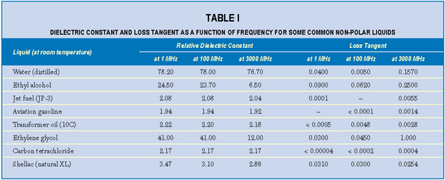
An interesting property of most material is the variation of measured K and tan d with frequency of the applied measurement voltage. For either homogeneous isotropic liquids or solids, the dielectric constant and loss tangent can be defined as the real (K = e') and imaginary (tan = e ") components, respectively, of the relative complex permittivity e = e ' + je ". Material absorption contributes the imaginary component to the dielectric constant e(w) = e'(w) + je"(w), where w is the angular frequency. For example, the dielectric constant of water depends on frequency, temperature and ion content. Dielectric absorption also occurs, becoming significant at about 500 MHz and passing through a maximum at approximately 17 GHz.2 Table 1 lists the dielectric constants and loss tangents of several common liquids at various frequencies.3 Note that the values for both loss tangent and dielectric constant range widely.
Temperature is also an important factor. For pure water at room temperature and at frequencies below approximately 500 MHz, e ' is about 80; this falls to approximately 60 at 170?F. Dissolved ionic materials (salts) lower the dielectric constant further. A saturated salt solution has a dielectric constant of approximately 50. Salts add conductivity s to the solution, which adds to the imaginary part of the dielectric constant such that
e (w ) = e '(w ) + [je "(w ) + s /w e 0 ]
This loss, if present, is important usually at the lower end of the radio frequency range only and is distinguished by the fact that this term in the loss tangent varies inversely with frequency. An increase in temperature increases the loss due to ionic conduction because of the increase in ionic mobility.4
A loss tangent peak occurring at a particular frequency is a characteristic of many liquids and materials. This peak is often accompanied by a rapid change in the dielectric constant. Both effects are the result of a resonance phenomenon occurring in polar materials. The position of the loss tangent peak in the frequency spectrum is very sensitive to temperature. An increase in the temperature increases the frequency at which the peak occurs. Nonpolar materials have very low losses without a noticeable loss tangent peak and the dielectric constant remains essentially unchanged over a wide frequency range.
A good description of dielectric constant and loss tangent properties of individual polymers can be found in the Encyclopedia of Polymer Science , Vol. 5. The chapter on electrical properties is especially useful.5 Nonpolymer materials and complex compounds exemplified by lubricating oils and other hydrocarbon mixtures may be expected to present an even more complicated response.
To complicate matters even further, it has been determined that when adding cube roots of the relative complex permittivities of mixture constituents (liquids or solids) in proportion to their volume fractions for a two-component mixture, it can be stated that
(e )1/3 = v1 (e 1 )1/3 + v2 (w 2 )1/3
where
w = permittivity of the mixture
w 1 = permittivity of the medium in which the particles of permittivity w 2 are dispersed
v1 and v2 = volume fractions of the respective components where v1 + v2 = 1
All of these variables and interrelationships imply that the factors affecting complex permittivities of multicomponent mixtures will produce unique measurement values that are a function of the chemical makeup of the liquid and the measurement system.6
EXPERIMENTAL INVESTIGATION
Recently, Southwest Research Institute (SwRI) initiated a small internal research project to investigate the potential for RF communication through liquids. The intent of the research was to determine if it was practical to design a short range radio frequency link that would provide communication though fluids. The intended user was the oil exploration community. To determine the expected communications range, various fluids encountered in drilling operations were studied to identify their RF characteristics. These fluids included oil- and water-based drilling mud in new and used (contaminated) condition. Studies included measurement of the loss tangent and relative dielectric constant as a function of radio frequency. Not surprisingly, SwRI engineers found that the measurements produced very different values of loss tangent and relative dielectric constant as a function of very slight differences in the chemical makeup of the samples tested.
Dielectric constant and loss tangent measurements were taken over the 100 to 3000 MHz range using laboratory test equipment (a network analyzer, dielectric probe and commercial software). Examples of some of the measurements taken during the internal research project are displayed. Figure 1 shows the loss tangent and relative dielectric constant of new motor oil (commercial 10W30) and old motor oil after approximately 2000 miles of engine use. For comparison, Figure 2 shows the dielectric constant and loss tangent of tap water over the same frequency range. Water is a potential sample contaminant. The RF dielectric and loss properties of water are very distinctive and easily recognized as quite different from natural and synthetic lubricants.7
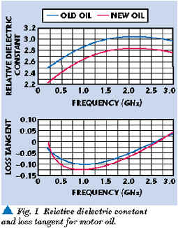

Note that in the motor oil data plot, the oil loss tangent is negative for some frequencies. The negative measurements are due to calibration inaccuracies evident when measuring small values of loss tangent (< 0.1). Nevertheless, relative differences between measurements are valid and readily apparent.
The measurements verified that the effects of the liquid (drilling fluid) chemical makeup on both the dielectric constant and loss tangent are extremely complicated. Whether such responses can be dissected to reveal the exact makeup of the liquid remains to be seen. However, it became apparent that a multi-frequency RF sensor can be very sensitive to minor variations in fluid composition.
MEASUREMENT SYSTEMS
Both relative dielectric constant and loss tangent can be accurately measured as a function of RF by conventional laboratory test equipment. For example, the model HP 8752C network analyzer together with the HP 85070M probe kit and special HP 85071B materials measurement software allow relative dielectric constant and loss tangent measurement at frequencies ranging from 300 kHz to as high as 6 GHz. All of this equipment is rather expensive, large and power hungry, but unnecessary if absolute measurements of relative dielectric constant and loss tangent are not required. A few simple liquid sensors do exist for special applications.
There has been some commercialization of RF liquid sensing, primarily for detection of water contamination in liquids and other materials. These efforts are exemplified by the Phase Dynamic Corp. water-cut meter and similar sensors produced by Agar Corp., Roxar, Aqua Measure Instruments Co. and others.811 Most of these sensors operate at a single frequency. Some are based on oscillator frequency and/or load variation as a function of material relative dielectric constant and loss tangent.12 Others determine water content by measuring only relative dielectric constant at a single frequency. Apparently, multi-frequency relative dielectric constant and loss tangent measurements have not yet found much application to commercial material sensing.
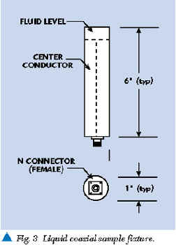
The HP 8752C and other multi-frequency analyzers are part of a large family of general-purpose impedance measuring devices. Most of these laboratory analyzers are based on conventional transmission line measurements of amplitude and phase differences between RF signals incident and reflected from a sample being measured. The fundamental components required for these phase and amplitude measurements are a sample fixture (as shown in Figure 3 ), an RF source, directional couplers, RF volt meters and a phase detector. Figure 4 shows how these items are configured. The liquid sample can be placed in an open coaxial test fixture. The RF source produces an RF signal incident to the sample being analyzed. One dual directional coupler port samples the incident signal for measurement by the first RF voltmeter. RF signal energy reflected by the liquid is sampled and measured at the other dual directional coupler port by the second RF voltmeter. A directional coupler is designed to isolate the incident signal from reflected signal. The phase detector determines the phase difference (in electrical degrees) between the incident and reflected signal.
With the ratio of the two measurements of RF voltages provided by a differential amplifier and measurement of the phase difference between the two RF voltages (incident and reflected), a value for the characteristic impedance of the sample/fixture combination can be calculated. The characteristic impedance of a sample is directly related to its relative dielectric constant and loss tangent, both of which can be calculated from the phase difference and amplitude ratio if the physical and electrical configurations of the sample and test fixture are known. The calculations themselves are rather involved, but deterministic and straightforward.13
If only measurement of relative differences between material samples is required, then there is no need to determine the absolute values of dielectric constant and loss tangent of each sample. The RF phase and amplitude measurements can be compared directly. This measurement technique can form the basis of an RF-based sensing system if the condition of the liquid sample can be related to its effect on the phase and amplitude measurements at various radio frequencies. This correlation of the condition due to contaminants (for example, soot, water, salts and metal) is the key to the design of a sensitive low cost, RF-based liquid sensing system.
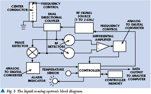
A flexible RF-based liquid sensor system could be designed by adding a simple microprocessor to the previously shown basic measurement block diagram. A separate temperature sensor may also be necessary to compensate for temperature-related measurement variation. The processor would take the voltage and phase measurements digitized by analog-to-digital converters and compare them to similar measurements in a processor database. When a set of amplitude and phase measurements is outside the expected range, an indication can be output via a data port for further analysis. It would also be easy to add a serial port so updated liquid data (new or improved limits) can be uploaded to the sensor internal database. Depending on the final actual sensor design, liquid data could also be input by keyboard or magnetic media. Figure 5 shows a block diagram of a complete RF-based sensor providing a simple GO/NOGO alarm.
By measuring the phase and amplitude of various liquid samples over a specific frequency range optimal for the liquid under test, a database of measurements can be established for acceptable liquids conditions. It may be possible to simplify the database measurements to a set of limits that would define acceptable conditions. The database limits would then allow detection of liquid changes by comparison of phase and amplitude measurements of liquid degraded by contaminants (soot, water, salts and metal) with the acceptable limits derived from the database.
FLOWING LIQUIDS
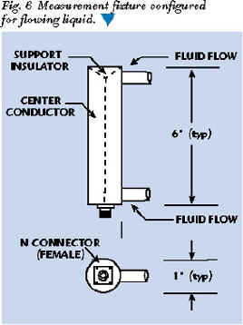
Flowing liquids present a special situation. The fixture must be designed to allow unrestricted liquid flow while maintaining a fixed RF measurement configuration. This can be accomplished in several ways. Perhaps the simplest is a modified coaxial fixture that allows the fluid to flow through it. The entry and exit openings should be much less than the expected wavelength in the liquid to minimize the effects of material outside the fixture. Mesh or gratings could be placed across the flow; however, this may be too restrictive for some fluids. Noncontact fixtures can be designed that essentially measure the total dielectric and loss tangent of the fluid flow and a dielectric pipe surrounding the fluid flow. This approach may be the most practical for many high dielectric/high loss liquids. Figure 6 shows a simple conversion of the coaxial fixture shown previously into a flowing fluid fixture.
CONCLUSION
It is apparent that measurement of relative dielectric constant and loss tangent as functions of frequency can determine much about a liquid sample. Absolute measurement of relative dielectric constant and loss tangent is not necessary to detect a change in sample composition. The complex impedance of a sample as a function of frequency contains the same information as relative dielectric constant and loss tangent. Design of a low cost sensor system based on measurement of the complex impedance of a liquid sample at many frequencies is very feasible. Although there has been some commercial application of these measurements for material sensing, there has been no significant effort to produce low cost multi-frequency sensors for volume applications. By combining measurements of complex impedance and a database of measurements, it should be possible to produce a sensing system that could detect, identify and quantify changes to liquids and other materials occurring in near real time. Such sensors could find applications ranging from monitors for vehicle oil condition to water system pollution alarms. *
References
1. service.shu.ac.uk/schools/sci/chem/tutorials/molspec/nmr1.htm
2. J.B. Hasted, Aqueous Dielectrics , Chapman and Hall, London, 1970.
3. Reference Data for Radio Engineers , Fourth Edition, International Telephone and Telegraph Corp., New York, NY, 1956, pp. 6870.
4. Reference Data for Radio Engineers , Fourth Edition, International Telephone and Telegraph Corp., New York, NY, 1956 p. 62.
5. Encyclopedia of Polymer Science and Technology , Vol. 5, John Wiley & Sons Inc., New York, 1966, pp. 528624.
6. S. Nelson, D. Lindroth and R. Blake, "Dielectric Properties of Selected and Purified Minerals at 1 to 22 GHz," Journal of Microwave Power and Electromagnetic Energy , Vol. 24, No. 4, 1989, p. 215.
7. A.R. Von Hipple, Dielectric Materials and Applications , John Wiley & Sons Inc. New York, 1954.
10. www.roxar.com/
11. members.aol.com/aquamoist/
12. Y.S. Yang, B.N. Scott and B.B. Cregger, "The Design, Development and Field Testing of a Water-cut Meter Based on Microwave Techniques," Production and Operations and EE Engineering Proceedings , SPE Annual Technical Conference and Exhibition, September 2326, 1990, New Orleans, LA, pp. 775780.
13. W.B. Webb and R.H. Church, "Measurement of Dielectric Properties of Minerals at Microwave Frequencies," Report of Investigations 9035 , United State Department of the Interior, Bureau of Mines, 1986, Library of Congress Number TN23.U43, No. 9035.
 Tom Warnagiris is a staff engineer at Southwest Research Institute, San Antonio, TX. He received his BSEE from the Pennsylvania State University in 1963 and from 1973 to 1975 performed graduate work at the University of South Florida. He holds several communications-related patents. Warnagiris is a registered professional engineer in Pennsylviania and a senior member of the IEEE. He can be reached at (210) 522-3746 or via e-mail: twarnagiris@swri.org.