A series of continuous modes for designing broadband high efficiency power amplifiers (PA) is described and a broadband PA based on this theory is realized. A new theoretical formulation is presented by shaping the drain voltage and current waveforms. In comparison to the classical series of continuous modes, wider design space is obtained, which is benefit for broadband matching network design. To verify this theory, a high efficiency PA is designed, built and tested. Measurement results verify that the objective performance is obtained, while fundamental and harmonics impedances are in good agreement with theory. The fabricated PA delivers 10.9 to 19.5 W saturation output power with a drain efficiency (DE) of 69.5 to 77.9 percent from 2.3 to 3.8 GHz. Gain is 9.8 to 12.3 dB with output power of 40.4 to 42.9 dBm.
PA designers seek broadband performance with high efficiency. Harmonic-tuned PA modes, such as class J and F, have become the primary candidates for obtaining high efficiency.1 Although these PAs mode can operate with efficiencies higher than 78.5 percent, they are limited to narrow bandwidths due to the requirement for accurate harmonic terminations. To broaden operating bandwidths and simplify matching network design, advanced PAs modes, known as class B to class J continuous2 and the family of continuous class F,3 have been proposed. With multiple impedances distributed over the desired bandwidth dynamically, these extended harmonic-tuned PA modes achieve the desired efficiency and output power. Based on these modes, there are various ways to obtain wideband operation.4-6
These continuous PA modes, however, simply expand the reactive part of the optimal impedance solution; therefore, the optimal impedance can only change on the constant resistance circle of the Smith chart. Just like the continuous class F mode, pure reactive second harmonic impedances are still required.
The series continuous modes (SCM) concept was presented by Chen et al. in 2014.7 By combining continuous modes, new modes provide the possibility of realizing a high efficiency broadband PA. The real part of the optimal fundamental impedances (Z(1f,re)) can vary from 1 to 1.154, providing greater design freedom.
In this article, new theoretical formulations based on the continuous class F mode and SCMs are presented by shaping the voltage and current waveforms. Compared to SCMs, the real part of novel series continuous modes (NSCM) can vary over a wider range, which significantly relieves the difficulty in broadband matching network design.
NOVEL SERIES CONTINUOUS MODES
Review of the Continuous Class F Mode
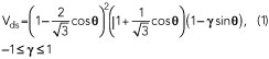
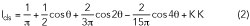
From the class F mode, the required unified drain voltage waveforms are defined in Equation 1. In order to sustain a positive voltage, empirical parameter γ is in the range of ‐1 and 1. The ideal normalized half-rectified drain current waveform3, 7 is shown in Equation 2.
A DE of 90.7 percent can be maintained while delivering maximum power and optimal impedances can vary on the Smith chart, but with a constant real part.
Review of the SCMs
By combining the continuous class B/J mode, the continuous class F mode and the other continuous modes, the normalized voltage formulation3,7 is defined by Equation 3 with the same ideal normalized half-rectified drain current waveforms as in Equation 2, formed by the class B bias condition.

To keep Vds positive, the relationship between α and β is shown in Equation 4.
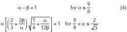
The theoretical DE varies from 78.5 percent (the continuous class B/J mode) to 90.7 percent (the continuous class F mode). The real part of the normalized fundamental optimal impedance varies from 1 to 1.154 (1 ≤ α ≤ 2/√3), which is good for realizing wideband operation.
Novel Series Continuous Modes
Starting from the continuous class F mode, the continuous class F‐1 mode is obtained by shaping the current waveforms while maintaining a constant voltage waveform. This expands the design space. Then, by multiplying the factor (1 – γ sinθ) with the drain voltage waveform, SCMs offer increasing flexibility. Evolving from the continuous class F mode and SCMs, the NSCMs perform shaping of the voltage waveform and the current waveform simultaneously as described by Equations 5 and 6.
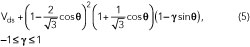

To work successfully, it is worth noting that non-zero crossing voltage and current waveforms are essential. So the γ parameter varies from ‐1 to 1, and the relationship between the α and β is as follows:
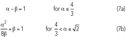
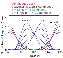
Figure 1 Normalized drain voltage and current of the novel series continuous modes.
The various combinations of α and β map to different continuous modes. When α = √2 and β = 1/2, the quasi-continuous class F‐1 mode is obtained. When α = 5/4 and β = 1/4, another continuous mode is achieved. The voltage and current waveform of α = 11/10 and β = 1/10 corresponds to another new continuous mode as well. The voltage and current waveforms when α = 11/10, 5/4 and √2 are depicted in Figure 1. The current waveform of continuous class F is also plotted in Figure 1 for comparison.
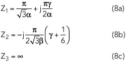
The fundamental and harmonic optimal impedances, normalized to Ropt, are given in Equation 8. Ropt = 2 ∙ (Vds – Vknee)/Ipeak is the optimal fundamental impedance for class B operation, corresponding to all harmonics short circuited.