

While large satellite-on-the-move (SOTM) communication systems operating at S-, C- and X-Band frequencies have been widely deployed in naval applications, the latest SOTM developments are focusing on much smaller configurations for tanks, armored personnel carriers and airborne platforms such as unmanned aerial vehicles (UAV). As well as a reduction in physical size, there is also a requirement for higher capacities and data rates, particularly for real-time high-definition video feeds, so Ka-Band frequencies are becoming the preferred choice. The Ka-Band SOTM terminal market is still in the early stages of prototype system build, test and qualification, but it is destined to develop over the coming years.
In order to track the satellite, each moving vehicle is equipped with a satcom antenna system mounted on a three-axis, stabilized pedestal. As it is essential for the main axis of rotation to have unlimited 360° movement, cables cannot be used to feed signals to and from the antenna reflector; the only option is a microwave rotary joint.
A key design goal for SOTM antenna manufacturers is to reduce the footprint and profile of antenna systems for the emerging Ka-Band applications. This is achieved by using small reflector antennas or flat panels and by changing the traditional antenna topology, moving the block up-converter (BUC) – which converts data at L-Band frequencies into a Ka-Band signal for transmission to the satellite – from the rotating side to the fixed side below the antenna pedestal (i.e., inside the tank). However, this does mean that the microwave rotary joint now has to handle the transmit frequency at full power with, of course, minimal loss. Down-converting the incoming signal from Ka-Band to L-Band is performed by a low-noise block converter (LNB), but since this is quite a small device, it can usually be accommodated above the pedestal without any difficulty.
To address these Ka-Band SOTM requirements, Link Microtek has added model AM28CORJD to its family of microwave rotary joints. This miniature dual-channel device features a high-power transmit channel implemented in a right-angle WR28 waveguide on the fixed (input) side and a female K-type coaxial connector on the rotating (output) side, while the receive channel uses two female SMA connectors. Located on the main axis of rotation of the antenna, the rotary joint measures 31.75 mm in diameter by 74.68 mm in height (excluding the 50 mm diameter UBR320 standard bulkhead flange) and normally has to fit within a confined space at the centre of the bore of a slip ring assembly that powers the antenna’s DC motors and other parts.
The central transmit channel of the AM28CORJD covers Ka-Band frequencies from 29 to 31 GHz and delivers excellent microwave performance, with a maximum power rating of 40 W CW, a typical insertion loss of only 0.6 dB and a maximum VSWR of 1.25:1. The L-Band receive channel uses two female SMA coaxial connectorsand normally operates over the 950 to 2150 MHz frequency range. It offers a microwave power rating of 1 W CW, a maximum DC current rating of
500 mA (for powering the LNB), an insertion loss of 0.25 dB and a typical VSWR of 1.5:1. Ka-Band SOTM systems utilize expensive solid-state power amplifiers to produce the output that is necessary to cope with adverse weather conditions or when the satellite is low down near the horizon. It is vital to avoid any significant loss of power in the path between the amplifier and the antenna, so insertion loss is a critical parameter for the rotary joint.
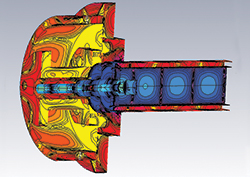
Figure 1 Electromagnetic simulation of internal waveguide-to-coax transition.
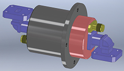
Figure 2 Alternative configuration with two right-angle WR28 waveguide bends.
Link Microtek uses electromagnetic simulation as part of the design process for its rotary joints (see Figure 1) in order to optimize the insertion loss, power-handling capability and other specifications. The simulation shows the internal waveguide-to-coax transition – a key section of the rotary joint – with the various colors representing field strengths ranging from high (blue) to very low (red). Akin to a mechanical watch, the internal construction of the rotary joint consists of over 40 very small individual parts, which are crafted to high precision and tight tolerances before being assembled and tuned by hand.
Despite its intricate design, the AM28CORJD is robustly constructed to withstand the particular mechanical stresses associated with SOTM systems – namely, occasional rapid movement when locking on to the satellite or if the vehicle turns a corner, combined with continual dither as the stabilized platform adjusts to maintain best lock on the satellite. Fabricated from aluminum to minimize weight, the rotary joint has an Iridite finish and its performance under extreme environmental conditions either meets or exceeds the requirements of MIL-STD-810G.
Other configurations of the Ka-Band dual-channel rotary joint can be supplied on request, customized to suit specific antenna requirements. The 3D CAD drawing in Figure 2 shows one possible alternative, utilizing space-saving right-angle WR28 waveguide bends on both sides of the transmit channel.
Link Microtek Ltd.
Basingstoke, UK
www.linkmicrotek.com