
R&S®RTE digital oscilloscopes offer fast and reliable solutions for everyday test and measurement tasks such as embedded design development, power electronics analysis and general debugging. Users benefit from features such as a high sampling rate of 5 Gsample/s, a high acquisition rate of one million waveforms per second and good signal fidelity. A comprehensive set of measurement and analysis tools delivers fast results, and the high resolution touchscreen makes the oscilloscope very easy to use.
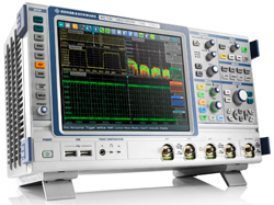
Shown in Figure 1, the R&S RTE is available with two or four channels and a bandwidth of 200 MHz, 350 MHz, 500 MHz or 1 GHz. It handles everyday test and measurement challenges quickly, accurately and easily, providing time domain, logic, protocol and frequency analysis in a single box.
Confident Measurement
The main purpose of a digital oscilloscope is to measure electrical signals. This can be simple measurement of signal characteristics such as frequency and rise and fall times or complex analysis such as determining the switching loss of a switched-mode power supply. The most important factor for users is that they can rely on the quality of measurement results.
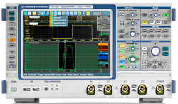
Figure 1 The R&S RTE is available with two or four channels and a bandwidth of 200 MHz, 350 MHz, 500 MHz or 1 GHz.
The more details an oscilloscope can show, the higher the probability that the user will be able to analyze signal faults or important events. As a prerequisite, the oscilloscope must have a high time resolution that is based on the sampling rate. In addition, many applications also require long record lengths, for instance for analyzing the data content of serial protocols.
In order to maintain a high sampling rate even for long signal sequences, the oscilloscope requires a deep memory. The R&S RTE offers a combination of a sampling rate of 5 Gsample/s at a memory depth of 10 Msample per channel. This can be optionally expanded to 50 Msample per channel.
The less often signal faults occur, the longer it can take to detect them. This makes a high acquisition rate critical. The core of the new oscilloscope is an ASIC that was especially designed for parallel processing. As a result, the R&S RTE can acquire, analyze and display more than one million waveforms per second without a special acquisition mode. The high acquisition rate makes it possible to find signal faults faster and more reliably, effectively shortening debugging time (see Figure 2).
Also, the highly accurate Rohde & Schwarz digital trigger system provides precise results. This system determines when a trigger condition is met by directly analyzing the digitized signal with 500 fs resolution independently of the current sampling rate. The result is very low trigger jitter (< 1 ps RMS) and high measurement accuracy. Thanks to the digital trigger system, the trigger hysteresis can be adjusted to the signal quality. This ensures, for example, stable triggering even on extremely noisy signals.
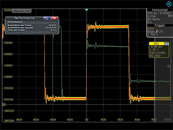
Figure 2 The R&S®RTE finds rare signal faults very quickly thanks to its high acquisition rate of one million waveforms per second.
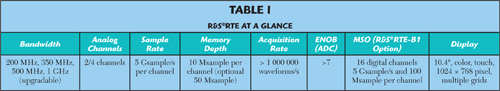
The single-core A/D converter with more than seven effective bits (ENOB) almost completely eliminates signal distortion. The input sensitivity of 1 mV/div without any bandwidth limitations ensures that low-amplitude signals can also be measured with a high degree of accuracy. The main features of the new oscilloscope are listed in Table 1.
More Functions, Faster Results
The R&S RTE includes many integrated measurement tools for detailed signal analysis. They range from simple cursor functions to mask tests to complex mathematical operations. Many measurement functions such as histograms, spectrum display and mask tests are hardware-implemented. This ensures a very responsive scope and a high acquisition rate. Furthermore, statistically conclusive measurement results are available fast.
In addition to the automatic measurements that are customary for digital oscilloscopes, the R&S RTE offers the QuickMeas function. QuickMeas simultaneously displays the results of several measurement functions, which users select according to their needs. A toolbar at the upper edge of the screen provides fast access to this function.
Mask tests reveal whether a specific signal lies within defined tolerance limits and use statistical pass/fail evaluation to assess the quality and stability of a device under test. Mask creation in the R&S RTE is simply a matter of pressing a few buttons. The high acquisition rate ensures that mask violations are detected rapidly and reliably. Signal anomalies and unexpected results are easy to identify by stopping the measurement if the mask is violated.
Where does the interference pulse in the signal come from? What caused the loss of a data bit? The real cause of a problem can often only be found by looking at the history of a signal sequence. The R&S RTE history function always provides access to previously acquired waveforms. This enables users to later analyze in detail the measurement data stored in the memory.

Figure 3 Together with the R&S HZ-15 near-field probe set, the R&S RTE oscilloscope is ideal for EMI debugging during development.
The FFT function of the new oscilloscope makes spectral analysis easy. The high acquisition and post-processing rate conveys the impression of a live spectrum, and operation is as simple as entering the center frequency, span and resolution bandwidth. Using the persistence mode, rapid signal changes, sporadic signal interference and weak superimposed signals can easily be made visible.
The ability to overlap FFT frames enables the R&S RTE to detect intermittent signals such as pulsed interferers. This powerful FFT function plus the high dynamic range and input sensitivity of 1 mV/div make the oscilloscope ideal for tasks such as EMI debugging of electronic circuits during product development (see Figure 3).
Easy to Use
Thanks to the high resolution 10.4" XGA touchscreen, users can intuitively perform their daily test and measurement tasks. For example, users can simply ‘drag & drop’ waveforms to arrange them on the screen. The screen can flexibly be divided into several diagrams according to the user’s requirements. Real-time miniature views of the signals on the edge of the screen allow users to always see what is happening.
The R&S RTE controls are color-coded and indicate which channel is currently active. The color coding corresponds to the signal display on the screen. Dialog boxes are opened as semi-transparent overlays over the active waveforms, which maintain their full size. Users can adjust the transparency of dialog boxes as required. Signal flow diagrams and forward and back buttons in the dialog boxes simplify navigation, while the configurable toolbar provides fast access to frequently used functions.
Users simply select a tool and apply it to their waveform. Tools that have a similar function are grouped together. In addition to the standard tool suite, the R&S RTE features many highlights such as fingertip zoom, which allows users to quickly view signal details by moving their finger or mouse along the signal. Another example is the SaveSet tool which enables users to quickly load different configurations. To select the right configuration, the user simply swipes a screenshot.
Dedicated Applications
In addition to the standard functionality, the R&S RTE offers various optional application solutions, including trigger and decoding options for serial buses (such as I2C, SPI and CAN) and a power analysis option. The logic analysis capability is essential for analyzing digital components of embedded designs. The R&S RTE-B1 mixed signal option can be added to any base unit and offers 16 additional digital channels with a sampling rate of 5 Gsample/s and a memory depth of 100 Msample per channel. It is possible to decode up to four serial or parallel buses simultaneously.
A comprehensive portfolio of high-quality active and passive probes is available for the R&S RTE to perform measurements in common voltage and current ranges. One of the highlights of the active probes is a micro button on the probe tip. This button can be used to perform a variety of functions such as run/stop, autoset and adjust offset on the oscilloscope. The highly precise R&S ProbeMeter DC voltmeter (measurement error: ±0.1 percent) is integrated into the active probe and provides a convenient means of answering questions such as: “Is the supply voltage correct?” and “Is DC voltage superimposed?”
Rohde & Schwarz,
Munich, Germany
+49 89 4129 12345,
www.rohde-schwarz.com