
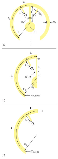
Figure 1 Layout of circular tri-mode resonators (a) CTMR, (b) even-mode equivalent circuit and (c) odd-mode equivalent circuit.
This article presents a compact microstrip bandpass filter (BPF), which consists of a circular tri-mode resonator (CTMR) and two meandering feed lines with both capacitive and inductive S-L couplings to obtain good harmonic suppression and multiple transmission zeros. A prototype of the proposed BPF, centered at 4.1 GHz, has been designed and fabricated. The measured results are in good agreement with the full-wave simulated ones.
Bandpass filters are essential building blocks for communication systems. To make the filters more compact, one can modify the traditional resonator to generate additional modes. Dual-mode resonators are attractive because each resonator can be used as a doubly tuned circuit and the number of resonators required for a given degree of filter is reduced by half, resulting in a reduced-size filter structure, which has been analyzed in depth.1,2 Triple-mode or other multi-mode resonator microstrip planar filters are developed from the simple dual-mode filters, as can be seen in the literature.3-7 With respect to feed-line coupling to resonators, there are also many coupling types. A compact dual-mode H-shaped filter with S-L coupling has been described.8 In addition, BPFs with only inductive S-L coupling and only capacitive S-L coupling have been proposed.9,10 However, these filters, using these conventional feeding types, generated at most four transmission zeros.
In this article, a compact BPF, using circular tri-mode resonator (CTMR), based on both capacitive and inductive S-L couplings, is demonstrated for the first time. The designed filter can generate six transmission zeros to suppress harmonics effectively by introducing capacitive and inductive cross-couplings between the input and output ports.
Resonator Analysis and Filter Design
As shown in Figure 1, the CTMR consists of a circular half-wavelength resonator, a pendulum-shaped open stub and two short stubs. Since the CTMR is symmetrical to the dashed line, it can be analyzed by even- and odd-mode methods as shown in the figure. Figure 2 shows the EM simulated frequency responses of the CTMR under weak coupling. When the open-stub length L1 increases, fodd1 is constant and feven1 barely varies, while feven2 moves toward a lower frequency within a wide range. When the short-stub length L2 increases, feven2 is fixed and fodd1 almost does not change, but feven1 decreases. According to the analysis, the first odd-mode resonant frequency fodd1 is independent of the open stub and the short stub, which is mainly determined by the electrical length (2(θ1+θ2)) of the circular resonator. The first (feven1) and second (feven2) even-mode resonator frequencies are mainly determined by the short stub and the open stub, respectively. So in the filter design, the basic structure parameters (such as R2, W3, θ1 and θ2) of the CTMR can be first decided to obtain the desired center frequency. Then, the open stub parameters (L1, W1 and R1) and the short stub parameters (L2 and W2) can be changed to realize the desired upper frequency and low frequency of the passband, respectively. The bandwidth of the filter, therefore, can be mainly determined by the structure parameters of the pendulum-shaped open stub and of the two short stubs.
Based on the CTMR, three BPFs with different S-L coupling types were designed as shown in Figure 3, where the dimensions of three CTMRs and the gaps between each coupling arm and CTMR were all the same. First, filter A was designed using CTMR with only capacitive S-L coupling and then filter B, using CTMR with only inductive S-L coupling. Both filters A and B demonstrate filtering characteristics with an inherent finite frequency transmission zero on the upper side of the passband and two additional transmission zeros located on each side of passband. However, the disadvantage of using these two coupling types is that the harmonic passband suppression is not good enough. There are, in both, undesired harmonic passbands at 10.7 GHz, which can be seen in Figure 4. Finally, an improved filter (filter C), with both capacitive and inductive S-L coupling, is proposed. It could generate more transmission zeros than filters A and B. Meanwhile, the 2nd harmonic passband at 10.7 GHz can be effectively suppressed to obtain a desirable upper stopband attenuation characteristic, achieving higher selectivity.
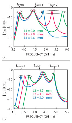
Figure 2 Simulated insertion loss of CTMR under weak coupling when varying L1 (a) and L2 (b).
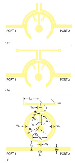
Figure 3 Layout of the tri-mode filters with different S-L couplings (a) only capacitive S-L coupling, (b) only inductive S-L coupling and (c) both capacitive and inductive S-L couplings.
The circuit model of the proposed tri-mode BPF, based on both capacitive and inductive source-load coupling, is shown in Figure 5. The signals transmitting from Port 1 (Source) to Port 2 (Load) have three paths. Path 1: the signal from Port 1 to Port 2 is mainly coupled into the CTMR through a parallel coupling-line structure; Path 2: the signal from Port 1 directly to Port 2 through a series capacitor is coupled weakly and exerts little influence on the passband; Path 3: the signal from Port 1 to Port 2 through a series inductor is also coupled weakly and exerts little influence on the passband. However, the interaction of the signals from the two sets of paths (Path 1 and Path 2, Path 1 and Path 3) may both generate finite transmission zeros beyond the passband. So this type of filter cannot only realize the tri-mode response, but also generate more transmission zeros than the other two BPFs using two conventional feeding styles, that is only capacitive S-L coupling and only inductive S-L coupling. The total admittance matrix of the filter can be given by:1
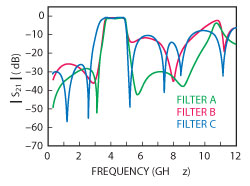
Figure 4 Simulated S21 of the three filters with different S-L couplings.
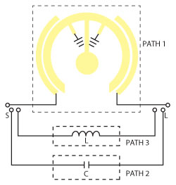
Figure 5 Circuit model of the proposed filter based on both capacitive and inductive S-L couplings.
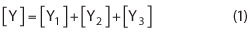
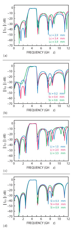
Figure 6 Simulated S21 of the filter vs. values of Lc (a), Sc (b), Li (c) and Si (d).
where [Y1], [Y2] and [Y3] are the admittance matrices of the Path 1, Path 2 and Path 3, respectively. In terms of the calculated admittance matrix, S21 of the filter can be derived by:1
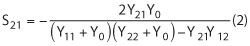
The finite transmission zeros are located at the angular frequencies where Y21 = 0 or Y211 = -Y212 - Y213, where Y211, Y212 and Y213 are the Y21 of the Path 1, Path 2 and Path 3, respectively. At these frequencies, the signals through two sets of coupling paths are all nearly out-of-phase.
Except for the inherent transmission zero, five additional transmission zeros are created by introducing capacitive S-L coupling and inductive S-L coupling. The location of these five transmission zeros can be controlled by the amount of the cross-coupling capacitance or inductance, which can be illustrated clearly in Figure 6. The gap Sc and the coupling line length Lc can adjust the amount of the capacitive S-L coupling, while the gap Si and the coupling line length Li adjust the amount of the inductive S-L coupling. As shown in the figure, when Lc, Sc, Li and Si vary, the inherent transmission zero barely changes, while some of the five additional transmission zeros will move. Therefore, the proper amount of the cross-coupling capacitance and inductance can be selected to adjust the location of the transmission zeros and to meet the required frequency selectivity.
Experimental Results
The proposed circular tri-mode BPF with both capacitive and inductive S-L coupling centered at 4.1 GHz has been fabricated on an RF-35 substrate with a relative dielectric constant of 3.5 and a thickness of 0.508 mm. The characteristic impedance of the input/output microstrip is taken as 50 Ω. The dimensions (mm) of the filter are chosen as follows: L1 = 3.6, L2 = 1.2, L3 = 5.4, Li = 2.5, Lc = 3.4, W0 = 1.1, W1 = 0.4, W2 = 0.3, W3 = 0.8, W4 = 0.6, Wg = 5, Wi = 0.6, Wc = 0.5, R1 = 1.2, R2 = 4, R3 = 4.9, Si = 0.6 and Sc = 0.2. θ1 = 28.3° and via radii are all r = 0.25 mm. The simulation and measurement are accomplished by using HFSS 13.0 and 8757D network analyzer, respectively. As shown in Figure 7, the measured results are in good agreement with the full-wave simulated ones. Slight deviations are observed, which could be attributed to fabrication error. At the center frequency of 4.1 GHz, the measured 3 dB bandwidth of the BPF is found to be 1.55 GHz (37.8 percent). The insertion losses, including the losses from two SMA connectors, are approximately 1.3 dB at the passband and the return losses within the passband are above 15.1 dB. Six transmission zeros are located at 1.13, 2.63, 5.17, 7.48, 8.44 and 11.14 GHz. Figure 8 shows a photograph of the fabricated filter.
Conclusion
A tri-mode BPF based on both capacitive and inductive S-L coupling with six transmission zeros is presented. Compared with the other two BPFs using two conventional feeding types, that is only capacitive S-L coupling and only inductive S-L coupling, this type of BPF cannot only possess a good tri-mode response, but also generate more transmission zeros to suppress the undesired harmonic passband.
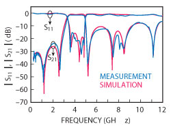
Figure 7 Measured and simulated results of the designed filter.
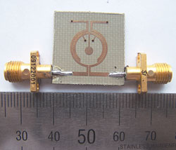
Figure 8 Photograph of the fabricated filter.
Acknowledgment
This work was supported by the China Scholarship Council (CSC).
References
- J.S. Hong and M.J. Lancaster, Microstrip Filter for RF/Microwave Application, John Wiley & Sons, New York, NY, 2001.
- J.S. Hong, S. Hussein and Y.H. Chun, “Dual-mode Microstrip Open Loop Resonators and Filters,” IEEE Transactions on Microwave Theory and Techniques, Vol. 55, No. 8, August 2007, pp. 1764-1770.
- K. Srisathit, A. Worapishet and W. Surakampontorn, “Design of Triple-mode Ring Resonator for Wideband Microstrip Bandpass Filters,” IEEE Transactions on Microwave Theory and Techniques, Vol. 58, No. 11, November 2010, pp. 2867-2877.
- W. Shen, X.W. Sun and W.Y. Yin, “A Novel Microstrip Filter Using Three-mode Stepped Impedance Resonator,” IEEE Microwave and Wireless Components Letters, Vol. 19, No. 12, December 2009, pp. 774-776.
- A. Torabi and K. Forooraghi, “Miniature Harmonic-suppressed Microstrip Bandpass Filter Using a Triple-mode Stub-loaded Resonator and Spur Lines,” IEEE Microwave and Wireless Components Letters, Vol. 21, No. 5, May 2011, pp. 255-257.
- X.H. Wu, Q.X. Chu, X.K. Tian and X. Ouyang, “Quintuple-mode UWB Bandpass Filter with Sharp Roll-off and Super-wide Upper Stopband,” IEEE Microwave and Wireless Components Letters, Vol. 21, No. 12, December 2011, pp. 661-663.
- L. Zhang, Z.Y. Yu and S.G. Mo, “Design of Compact Triple-mode Bandpass Filter Using Double Center Stubs-loaded Resonator,” Microwave and Optical Technology Letters, Vol. 52, No. 9, November 2010, pp. 2109-2111.
- F. Xiao, X.H. Tang, L. Wang, and T. Wu, “Compact Dual-mode H-shaped Filter with Source/load Coupling for Harmonic Suppression,” Microwave and Optical Technology Letters, Vol. 52, No. 6, June 2010, pp. 1431-1434.
- C.L. Wei, B.F. Jia, Z.J. Zhu and M.C. Tang, “Hexagonal Dual-mode Filter with Four Transmission Zeros,” Electronics Letters, Vol. 47, No. 3, 2011, pp. 195-196.
- J. Wang, Y.X. Guo, B.Z. Wang, L.C. Ong and S. Xiao, “High-selectivity Dual-band Stepped-impedance Bandpass Filter,” Electronics Letters, Vol. 42, No. 9, 2006, pp. 538-539.