
 | |||
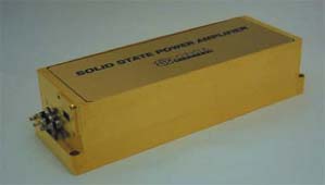
A breakthrough in Ka-band SSPA power is available for commercial and military applications. The Sophia Wireless model MPC4-2531 solid-state power amplifier (SSPA) provides 27 W of saturated power at 30 GHz and wideband coverage of 24 to 27 W at P3dB over 25 to 31 GHz. Linear performance is also exceptional at 20 W over most of the band. The new SSPA’s P1dB and P3dB are shown in Figure 1.
One of the most important considerations in designing such a high power amplifier is thermal management. The MPC4-2531 SSPA has a micro-thermistor mounted directly beside each of the active devices to monitor the thermal conditions in real time. A special base plate is used with several temperature sensors embedded at various locations to monitor the thermal behavior of the SSPA. Measurements can be taken under a variety of operating conditions. Based on this data, the transistor channel temperature is determined versus base plate temperature, as shown in Figure 2. The calculated MTBF is shown in Figure 3.
 | ||
| Fig. 1 The model MPC4-2531 SSPA’s RF output power. | ||
 | ||
| Fig. 2 The model MPC4-2531 SSPA’s thermal performance. | ||
 | ||
| Fig. 3 MTBF vs. base plate temperature. | ||
Linearization techniques are used to optimize intermodulation distortion (IMD) performance of multi-chip SSPAs. The IMD performance of the model MPC4-2531 SSPA at 29 to 30 GHz is significantly enhanced with state-of-the-art linearizers offering an additional 5 dBm in IMD performance.
Physical Construction
Multiple levels of device combining are required for high power SSPAs. Minimizing line lengths within each combiner path enables lower losses and smaller SSPA configurations. The lower losses result in higher power efficiencies and reduced power supply requirements, ultimately providing a lower cost SSPA.
Control and Monitoring
Smart SSPAs include microprocessor-based control and monitor circuitry to provide intelligence for system analysis and performance control. A significant reduction in thermal heat is accomplished by back-off from RF saturated power or shutting down the SSPA when not in use. The SSPA’s controls include RF on/off, power supply, and SSPA and driver amplifier controls. Its monitoring includes RF forward power, RF reflected power, temperature and primary current.
Low Voltage Power Supply
The SSPA requires low DC voltages, typically 6 to 8 V. Compact, industry-standard DC-to-DC converters with high efficiency are used to allow operation from any desired input voltage, such as 28/48 VDC or 115/230 VAC. Internal sequencing, regulation and protection smoothes line noise or ripple and protects the SSPA from over- or reverse-voltage.
The noise generated from switching a transistor on and off is extremely low, particularly in comparison to a TWT-based amplifier. The typical noise figure of an operating SSPA measures 6.0 dB at 28 GHz, and when switched to the pinch-off state, the output noise essentially drops to the thermal (300K) level.
For pulsed applications, it is frequently required to switch the amplifier on and off. Due to the low voltages involved, this can be accomplished easily and quickly in the SSPA. In order to switch from an operating state to a pinch-off state, the change in gate voltage required is under 1 V. The model MPC4-2531 SSPA module specification is shown in Table 1.
 | ||
Conclusion
The compact size, reliability and low voltage operation obtained from solid-state makes this SSPA a compelling solution. Further details are available at www.sophiawireless.com.
Acknowledgment
This development was supported by the Army Research Office.
Sophia Wireless Inc.,
Chantilly, VA (703) 961-9573, www.sophiawireless.com.