
A bandpass filter is proposed, miniaturized by composite right- and left-handed (CRLH) zeroth order resonators (ZOR), which form a cascaded triplet (CT) to have a significantly sharp skirt for high frequency selectivity. A fifth order UHF bandpass case is tested. First, an in-line ZOR bandpass filter is designed, whose total size is almost 20 percent of a parallel-edge coupled filter. Second, multiple transmission zeros (TZ) are created by changing the three innermost ZORs of the in-line filter to a CT. As a result, with an insertion loss better than 1.5 dB and a return loss better than 15 dB, the size-reduction effect and the skirt of the proposed filter are 24 times smaller than a lower-order parallel-edge coupled filter and as sharp as a 10th order Chebyshev filter. The simulation and measurement validate the proposed design method and the CRLH ZOR properties are proven by the no-phase variation electric field and dispersion diagram.
As the social and business network is expanded and globalized, the demands and users of mobile communications increase by the day. Mobile communication uses several channels, which should be isolated from the adjacent channels. In wireless communication systems, high selectivity of a channel is made possible by bandpass filters with sharp skirts.
Quendo et al introduced a combline filter with a small occupied size and sharp frequency selectivity.1 Vince also brought the design of a combline filter to have channel selectivity and reduced size.2 But the performance of the combline filters was not completely optimized. Their design can be improved with TZs near the passband edge, like the gapped and coupled loop filter Park et al showed.3 However, their filter does not have a steep skirt and has a narrow matched band, due to the fact that its transfer function has a low order and TZs are not in the effective vicinity of the passband. Tang used multiple resonators to increase the order of the bandpass filter and loaded the structure with capacitive coupling elements to determine the locations of TZs and obtained a steeper skirt in the form of a stacked parallel-edge coupled filter.4 In line with increasing the order of a filter, multiple resonators or modes are adopted and cascaded in groups, with cross-coupling paths (CCP) embedded to maximize the frequency selectivity and minimize the overall size, in the name of cascaded quadruplet (CQ), cascaded triplet (CT), etc.5-8 In most cases, CT and CQ methods go with waveguide cavity filter and multiplexer development and their synthesis scheme is described, accompanying the frequency responses with extremely sharp skirts due to high quality factors, TZs and filter orders.5-7
A CT filter can be made with microstrip lines, which has a center frequency of 1.05 GHz.8 The CCP of the CT results in a TZ and steepens its skirt. All the aforementioned filters have restrictions in significant size-reduction, since their resonators are multiples of half-wavelength, determined by the frequency of interest. Particularly, waveguides are not proper for the commercial communication bands such as the UHF, PCS, DCS and ISM. To overcome the limitations of the conventional design methodologies, metamaterials can help RF component designers.9-12 Since the CRLH lines and ZOR were suggested by Caloz et al,9 the no-phase variation phenomenon as B = 0 and the nonlinear dispersion relation have been used to design sub-wavelength resonators and compact filters.10,12 The CRLH ZOR filters and the ENZ and MNZ filter11 show improvement in reducing the size, but have relatively low frequency selectivity.
In this article, a compact CRLH ZOR bandpass filter is designed to have a remarkably enhanced frequency selectivity, working in the UHF band. First, a fifth order in-line ZOR bandpass filter is designed as the initial step. In this step, it is shown that the overall size of the initial filter is approximately 20 percent of that of a parallel edge coupled filter and the metamaterial characteristics are verified by the no-phase varying electric field and the dispersion diagram of the ZOR through simulations. Second, to have a steep skirt, a CT is formed by providing the phase-difference type of cross-coupling in the three innermost ZORs of the in-line ZOR filter, which creates TZs in the proximity of the passband edges. A further size-reduction due to the CT formation is addressed, with the total size of the proposed filter 24 times smaller than even a fourth order parallel edge coupled filter, along with the high frequency selectivity equivalent to the 10th order Chebyshev filter. Besides, the low insertion loss better than 1.5 dB and the low return loss better than 15 dB are obtained with a lossy FR-4 substrate. To examine the validity of the proposed design method, the circuit and 3D EM simulations are carried out and are in good agreement with the measurements of the fabricated prototype of the CT CRLH ZOR bandpass filter.
Design of the In-line CRLH ZOR Bandpass Filter
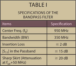
The bandpass filter is designed on the basis of the specifications shown in Table 1. The GSM communications in the UHF band require that fue, as the band upper edge, equals f0 + BW/2. To avoid the unwanted interference from the PCS, S21 should be attenuated to lower than -20 dB at the frequency fue + 50 MHz. The sharp skirt will be excluded in this step to design the in-line ZOR bandpass filter, but will be included in the next step. To begin with, the aforementioned specifications, except for the skirt, can be obtained with the following transfer function:
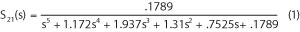
where s is jw and w is the angular frequency.
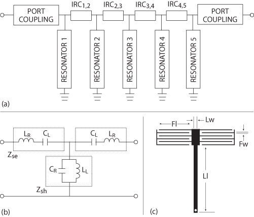
Figure 1 Equivalent circuit (a), CRLH equivalent circuit of the CRLH ZOR resonator (b), and its physical shape (c).
The fifth order equivalent circuit is shown in Figure 1. It comprises resonators 1 through 5 and their coupling elements named IRCi,j, which means that the inter-resonator coupling is between resonators i and j. Each resonator is made of a shunt inductor and capacitor. IRCi,j is chosen as a series inductor. In the conventional filter design, the physical structure for the resonators will be half-wavelength open-ended microstrip. But here, the CRLH ZOR for each of the resonators and the ordinary shunt inductor and capacitor in the resonator should be changed to the CRLH configuration, following the formula given by Jang and Kahng,10 with the following equations for the band-edge (or cut-off) frequencies, center frequency and impedance of the CRLH ZOR.
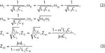
where the subscripts R, L, se and sh are the right-handed, left-handed, series and shunt, in that order.
The circuit elements for the CRLH ZORs 1 through 5 are calculated as CL = 1.31 pF, CR = 0.70 pF, LL = 7.37 nH, LR = 0.80 nH for ZOR 1 and ZOR 5, CL = 1.34 pF, CR = 1.40 pF, LL = 5.67 nH, LR = 0.50 nH for ZOR 2 and ZOR 4 and CL = 1.31 pF, CR = 0.70 pF, LL = 7.43 nH, LR = 0.80 nH for ZOR 3. These circuit elements are converted to the initial values of the physical dimensions using the following approximate formulas considering a microstrip on a 50 mil thick substrate of relative dielectric constant 4.4.
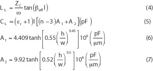
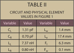
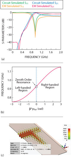
Figure 2 S21, S11 (a), dispersion diagram (b) and field distribution (c) of the CRLH ZOR.
The physical dimensions are varied from the initial values in the 3D EM simulation and reach the final values, when they give the center frequency at the desired value (950 MHz). The final physical dimensions are summarized for ZORs 1 and 5 in Table 2. With these values, the S21 and S11 parameters of ZOR, the dispersion diagram, and the metamaterial field distribution are shown in Figure 2. The figure reveals that the ZOR is appropriately implemented to resonate at f0 and the circuit simulation agrees well with the 3D EM analysis result of the ZOR, whose size is
0.05λg(with respect to f0). It is noted that because this is the resonator level, the desired passband will be made in the upcoming level for a complete filter. The dispersion diagram, which has btimes the unit-cell length vs. frequency, shows B=0 as the ZOR coincides with f0. Besides, the right- and left-handed regions occur beyond and below the ZOR as the positive and negative B, respectively. Together with the dispersion diagram, another property of this CRLH metamaterial structure is given as the no-phase variation electric field. All the field vectors of B=0 have the same direction at the ZOR frequency point.
Until now, the resonators have been addressed. Now, the coupling between neighboring ZORs is added to make a filter with the passband and stopband satisfying the specifications. In a symmetric in-line bandpass filter, the outer and inner inductive lines, named LIRC in Figure 3, of 3.0 and 3.8 nH as the initial numbers for IRC1,2 and IRC2,3, respectively, are considered and varied in the iterative 3D EM simulations until the bands are made close to and coincident with the specifications.
The inductive line can be realized by the inductance from the distributed transmission line, as shown in the figure, not needing the extra inductance of a lumped element like a chip inductor. So the filters are fully printed throughout this article.
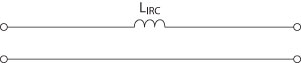
Figure 3 Equivalent circuit of the inductive coupling between ZORs.
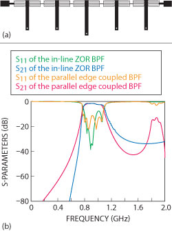
Figure 4 Geometry (a) and S-parameters (b) of the fifth order in-line CRLH ZOR filter.
The in-line filter in Figure 4 has five of the ZORs proposed with the coupling elements to effectively miniaturize the overall size. In detail, the total length of the proposed in-line filter is less than 65 mm, while one resonator of the conventional parallel edge coupled filter is approximately 90 mm long. This means a significant effect in the size reduction brought by the present work. In the next section, the size will be further reduced by taking the form of a CT. As another benefit, this in-line ZOR filter provides that the first harmonic at 1.9 GHz (=2f0) of the parallel edge coupled filter is shifted away and the stopband is widened for the in-line ZOR filter, which the nonlinear dispersion accounts for. With regard to the insertion loss and the return loss, the related specifications are not satisfied with the in-line filter, but this is the first step in the entire design of this article, and this matter will be mitigated in the next step. Also, the smoothly varying skirt
(S21 = -11 dB at fue+50 MHz) will be totally changed in the upcoming section.
Design of the Proposed CT ZOR Bandpass Filter

Figure 5 Schematic of the proposed CT ZOR bandpass filter (a), the preliminary shape of the filter (b), Y21,seq (c) and S-parameters (d).
Compliant to the passband, insertion loss and return loss of the specifications, the initial design as the fifth order in-line ZOR filter must be improved for steeper skirts with this configuration. The schematic of Figure 5 looks similar to that of Figure 1, but it becomes different as the three innermost ZORs (ZOR two, three and four) from the first design step are grouped into a CT, which plays the key-role in generating TZs, by providing the phase difference between the sequential path and cross-coupling path (CCP). The figure also shows the CCP for the CT. As the preliminary CT ZOR filter, the line parallel coupled to the stubs from the interconnection between the ZORs two and three and another from ZORs three and four is the CCP that couples ZORs two and four. To find the geometric elements of the preliminary CT ZOR filter, the goal is set at the TZs from Y21,seq + Y21,ccp = 0 to be located in the vicinity of the band edges for the purpose of increasing the slope of the skirt, according to the specification, and vary the important physical dimensions until the goal is achieved. The TZ points where Y21,seq is equal to -Y21,ccp are shown. These frequency points are shown to be the same TZs of the S-parameters. In addition, the skirt becomes much steeper by more than 10 dB, owing to TZH1. This is made possible with the physical dimensions shown in Table 3.
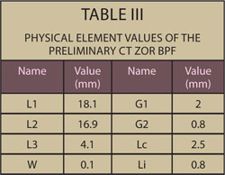
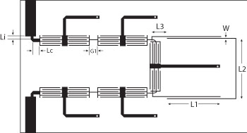
Figure 6 Final, folded CT ZOR bandpass filter.
If the preliminary shape of the proposed CT ZOR bandpass filter is examined, there is still room for reducing its total length. The preliminary structure can be folded with reference to ZOR three, while not distorting the previous frequency behaviors and the improved skirt. Figure 6 is the folded version of the preliminary structure of the proposed CT ZOR bandpass filter. Obviously, it undergoes a change in S21 and S11, due to the accompanying structural change in IRC2,3, IRC3,4, etc. So it is inevitable to correct the bandpass filter through another optimization.
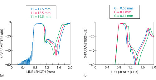
Figure 7 S21 vs. line length of the CCP in the CT (a), vs. the gap of the interdigital lines (b).
As shown in Figure 7, S21 is mainly influenced by L1 in terms of the bandwidth and skirt, due to change of TZH1, and slightly by L2 and L3. Simultaneously, the variation of the interdigital lines’ gap affects the TZs more seriously. With these observations, other geometrical parameters are adjusted to provide the optimal performance. They are finalized as Li = 0.8 mm,
Lc = 1.6 mm, L1 = 18.6 mm, L2 = 16.9 mm, L3 = 4.1 mm, G1 = 2.3 mm, G2 = 0.8 mm, G3 = 0.45 mm, W = 0.1 mm. As is shown in Figure 8, the passband is obtained as specified before, and the insertion loss and return loss are 1.2 dB and 15 dB, respectively. Especially, S21 has an attenuation of greater than 20 dB at fue+50 MHz by creating TZs. Including this finding, the 3D EM analysis results, as well as circuit simulation, are validated by comparison with the measurement of the fabricated prototype.
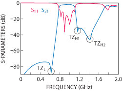
Figure 8 Simulated S11 and S21 of the final CT ZOR bandpass filter.
Taking advantage of a simple microstrip structure and feasible geometric parameters, the manufacturing cost is very low. As shown in Figure 9, the area of the prototype is estimated to be 74 × 33 mm, which is small for a UHF-band printed RF component. The measurements meet the target specifications and agree well with the 3D EM simulation, without manual tuning at the time of testing. The passband has an insertion loss better than 2 dB and the return loss is better than 15 dB. The sharp skirt is achieved with S21 greater than 20 dB at the specified frequency point. Mentioning the insertion loss, it is very low despite using FR-4 as a lossy and cheap substrate. Lastly, to clearly show the advantages of the proposed CT ZOR filter over the conventional methods, the total size, passband performance and skirt are compared between the two cases. Apparently, the proposed CT ZOR bandpass filter is smaller than 1/7 of the parallel edge coupled bandpass filter as compared in Figure 10. The proposed filter has a much steeper skirt than the conventional filter. Furthermore, to find out how high the order of a conventional filter should be to have the same frequency selectivity as the proposed filter, it is uncovered that the slope of a 10th order conventional Chebyshev filter is the closest to the proposed filter. In other words, the proposed filter has five resonators, but its effect is equivalent to the 10th order Chebyshev as:

Figure 9 Photograph of the fabricated filter (a) and measurements vs. 3D EM simulation.
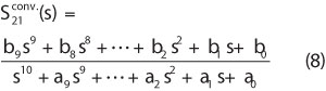
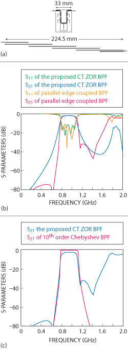
Figure 10 Comparison of sizes (a), S-parameters (b) and skirt (c) of the proposed and conventional filters.
where the coefficients are a9 = 1.14, a8 = 3.15, a7 = 2.71, a6 = 3.44, a5 = 2.14, a4 =1.53, a3 = 0.63, a2 = 0.24, a1 = 0.049, a0 = 0.0059, b9 = b8 = b7 = b6 = b5 = b4 = b3 = b2 = b1 = 0.0 and b0 = 0.0059. The indication is that a very high rate of miniaturization is achieved by the function of the 10th order filtering from the physically fifth order filter.
Conclusion
This article proposed a bandpass filter made very compact by implementing the CRLH ZORs and their coupling and forming a CT to have a steep skirt for high frequency selectivity. First, an in-line ZOR bandpass filter was designed as the initial step, whose total size is nearly 20 percent of the parallel-edge coupled filter. Second, the CT and its TZs were provided for improving the skirt of the initial ZOR filter. As a result, with the insertion loss better than 1.5 dB and the return loss better than 15 dB, the size-reduction effect and the skirt of the proposed filter were 24 times smaller than even a fourth order parallel-edge coupled filter and as sharp as a 10th order Chebyshev filter, respectively. The simulation and measurements validated the proposed design method, and the CRLH ZOR properties were proven by the no-phase variation electric field and dispersion diagram.
Acknowledgment
S. Kahng, the lead author, thanks the University of Incheon Research Promotion Program for their support.
References
- C. Quendo, E. Rius and C. Person, “Narrow Bandpass Filters Using Dual-behavior Resonators,” IEEE Transactions on Microwave Theory and Techniques, Vol. 51, No. 3, March 2003, pp. 734-743.
- A.D. Vince, “Practical Design Approach to Microstrip Combline-type Filters,” IEEE Transactions on Microwave Theory and Techniques, Vol. 22, No. 12, December 1971, pp. 1171-1181.
- S.J. Park, K.V. Caekenberghe and G. Rebeiz, “A Miniature 2.1 GHz Low-loss Microstrip Filter with Independent Electric and Magnetic Coupling,” IEEE Microwave and Wireless Components Letters, Vol. 14, No. 10, October 2004, pp. 496-498.
- C.W. Tang, “Design of a Microstrip Filter Using Multiple Capacitively Loaded Coupled Lines,” IET Microwave Antennas and Propagation, Vol. 1, No. 3, June 2007, pp. 651-657.
- R. Levy, “Direct Synthesis of Cascaded Quadruplet (CQ) Filters,” IEEE Transactions on Microwave Theory and Techniques, Vol. 43, No. 12, Part 2, December 1995, pp. 2940-2945.
- R. Hershtig, R. Levy and K. Zaki, “Synthesis and Design Of Cascaded Trisection (CT) Dielectric Resonator Filters,” 1997 European Microwave Conference Digest, pp. 784-791.
- S. Kahng, M. Uhm and S. Lee, “A Dual-Mode Narrow-Band Channel Filter and Group-Delay Equalizer for a Ka-Band Satellite Transponder,” ETRI Journal, Vol. 25, No. 5, October 2003, pp. 379-386.
- M.V. Nedelchev and I.G. Iliev, “Accurate Design of Triplet Microstrip Square Open-Loop Resonator Filters,” Microwave Review, Vol. 12, No. 2, November 2006, pp. 36-40.
- C. Caloz and T. Itoh, Electromagnetic Metamaterials: Transmission Line Theory and Microwave Applications, Wiley-Interscience, Somerset, NJ, 2006.
- G. Jang and S. Kahng, “Design of a Dual-band Metamaterial Bandpass Filter Using Zeroth Order Resonance,” Progress in Electromagnetics Research C, Vol. 12, 2010, pp. 149-162.
- B. Lopez-Garcia, D.V.B. Murthy and A. Corona-Chavez, “Half-mode Microwave Filters Based on Epsilon Near Zero and Mu Near Zero Concepts,” Progress in Electromagnetics Research, Vol. 113, 2011, pp. 379-393.
- G. Jang and S. Kahng, “Design of a Metamaterial Bandpass Filter Using the ZOR of a Modified Circular Mushroom Structure,” Microwave Journal, Vol. 54, No. 5, May 2011, pp. 158-167.