
 | |||
Since the mid-1940s, there have been requirements for test sources above 50 GHz. Magnetrons were first pressed into this application during the early to mid-50s, and by the middle of the decade, some manufacturers, such as Demornay Bonardi, were constructing multipliers using a cartridge diode with a window milled into the side of the diode package barrel to extend the frequency range of X-band (8 to 12.4 GHz) sweepers to 100 GHz and beyond. Toward the end of the 50s, commercially viable klystrons were coming into use as test sources. These reflex klystrons continued to occupy a significant position in the testing world, and by the mid-80s, reflex klystrons were available up into the 100s of gigahertz. Backward wave oscillators (BWO) became available above 50 GHz in the late 60s and were generally used with the Alfred series of sweep generators. Starting in the late 70s Siemens produced a commercial line of BWOs up to 170 GHz. These tubes were most often used with the Micronow 705 series millimeter-wave sweepers.
Aside from the Hughes impatt-based sweepers, tubes generally reigned supreme until the early 80s when relatively lower noise solid-state multipliers began to be commercially available. In the mid-80s, both Hewlett-Packard (now known as Agilent) and Watkins-Johnson introduced their solid-state multiplier assemblies with frequency coverage to 60 GHz, and by 1987, HP introduced two solid-state multiplier modules, affectionately known as the “Armadillos.” These solid-state multiplier modules provided frequency coverage from 50 to 75 GHz and 75 to 100 GHz, and were the first viable bench top (as apposed to rack mount) millimeter-wave test sources. In 1990, the 75 to 110 GHz Armadillo was introduced. OML (Oleson Microwave Labs) introduced its “Reflectometer” series of sources covering 50 to 75 GHz and 75 to 110 GHz in 1992 and a 60 to 90 GHz unit shortly thereafter. By 1997, OML had solid-state multiplier sources available up to 220 GHz as part of its VNA frequency extension product line, and in 2000 VNA frequency extension modules up to 325 GHz were available.1
In recent years, many applications have required highly stable and repeatable signal sources. Development of technology for use in space, such as space-borne radiometers, requires stable signal sources as local oscillators for mixer testing and as test sources for antenna and receiver testing. One of the requirements contained in the International Standards Organization (ISO) guidelines is that a calibration/certification lab confirm the ability of its test system to perform the required tests prior to any testing of the device-under-test (DUT). This has created a demand for a signal source with high repeatability in frequency and output power as the reference source or a comparison signal. Millimeter-wave semiconductor device testing at wafer level demands a high performance signal source that is small enough to be mounted in the wafer probing station to minimize the transmission cable or waveguide losses. Material characterization/analysis has, for a long time, used klystrons and BWOs as their millimeter-wave sources but more compact and stable solid-state sources are needed to replace the limited life thermionic devices.
 | |||
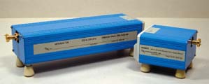
| Fig. 1 The OML Source Module being used to extend the frequency range of a lower frequency signal generator. | |||
Today signal generators with frequency coverage to 50 GHz are widely available. However, above 50 GHz, signal generators or existing extension source modules do not provide the necessary performance to meet the user’s requirements. Frequency coverage, output power, spurious outputs, reliability, size and cost are the often cited factors in not being able to satisfy the user’s requirements.
The new OML Source Modules, shown in Figure 1, are a series of small high performance millimeter-wave multiplier assemblies that extend a 20 GHz signal generator to cover the most heavily used waveguide bands from 50 to 325 GHz. Not only will these new Source Modules produce full waveguide band signals with frequency stability identical to the driving source, they are also designed to maintain a highly stable and repeatable output power. These properties allow their use as signal sources where repeatability is of paramount importance. Their small size makes them the perfect candidates for applications such as bench sources, wafer probing sources and remotely mounted sources for antenna testing.
Product Description
OML Source Modules carry on the philosophical intent of OML’s other product lines in that they are designed to expand the capability of a lab’s existing equipment. These Source Modules are compatible with any signal generator covering 8 to 20 GHz with an output power of +10 dBm.
A +12 VDC supply with 2 amp capability is all that is required to energize the modules. In some later model signal generators, the DC power source may be available directly from the signal generator. The RF drive signal may be either CW or swept frequency and the modules are capable of reproducing pulse, phase or frequency modulation.
 | ||
| Fig. 2 Typical Source Module output power vs. frequency in waveguide bands. | ||
Contiguous frequency coverage is available from 50 to 325 GHz with many of the straddle bands also available (see Table 1). The OML Source Modules achieve full waveguide bandwidths using chains of discrete multipliers. Modules for the higher millimeter-wave bands, above 110 GHz, make use of the efficient doublers and triplers developed for the 50 to 75 GHz, 60 to 90 GHz and 75 to 110 GHz modules as drivers for the output doublers and triplers. Typical output power vs. frequency available can be seen in Figure 2.
| ||||||||||||||||||||||||||||||||||||||||||||||||||||||||||||||||||||||||||||||||||||||||||||||||||||||||||||||||||||||||||||||||||||||||||||||||||||||||||||||||||||||||||||||||||||||||||||||||||||||||||||||||||||||||||||||||||||||||||||||||||||||||
The OML Source Modules make use of the signal source multiplying chains developed for the highly successful OML VNA2 T/R Frequency Extension Modules. The use of the same multiplier components has allowed for a greater economy of scale to be applied to both product lines. The Source Module output power is typically 2 dB higher than that of the VNA2 T/R module.
 | |||
| Fig. 3 A Source Module shown with the OML VNA2 T/R module. | |||
The package design utilized is the same housing that was developed for the OML VNA T Module with the addition of the heat sink assembly developed for the OML VNA2 T/R Module. The four adjustable height feet of the VNA2 Modules have been applied to the Source Module. Figure 3 shows a Source Module displayed with the OML VNA2 T/R Module.
Source Module Design
The OML Source Modules are made up of a series of multipliers. To mitigate the ripple caused by the interconnecting cable coming from the signal generator, all Source Modules are equipped with an input isolator. The Source Module’s first multiplier stage consists of a balanced doubler driving a multistage high power amplifier. These doubler/power amplifiers employ design techniques that result in a very stable power output vs. temperature characteristic. The doubler/power amplifier output stage uses a high performance high pass filter to ensure suppression of input frequency energy and its balance was carefully addressed to achieve low harmonic output contamination. Also, special attention was paid to the design of this stage to ensure that the output match characteristics were acceptable and repeatable. To provide the best possible output match, an output isolator is incorporated into each of the Source Modules below 220 GHz. The only reason for not having an output isolator in the 220 to 325 GHz module is the lack of WR-03 isolator availability in the marketplace.
A second balanced doubler is used as the output stage for the 50 to 75 GHz Source Module and the output interface is WR-15 waveguide. The 60 to 90 GHz module utilizes a balanced tripler as an output device with a WR-12 waveguide output interface. A tripler is also used as the output device in the 75 to 110 GHz Module and the output interface is WR-10 waveguide. The balance and output match characteristics of these multipliers ensure a typical 20 dB suppression of all subharmonics. The frequency coverage of these three Source Modules actually extends above and below the specified limits of their waveguide bands. This extended frequency capability and flat and stable output power are used to help achieve the full waveguide band performance of the next higher frequency group of modules.
The 90 to 140 GHz Source Module consists of an extended frequency WR-15 multiplier chain driving a balanced doubler with a WR-08 waveguide output interface. In similar fashion, the 110 to 170 GHz module uses an extended frequency WR-12 multiplier chain driving a balanced doubler, and its output interface is WR-06 waveguide. The 140 to 220 GHz Source Module uses a balanced doubler as the output device with the extended band WR-10 multiplier chain as its driver. The 140 to 220 GHz output interface is WR-05 waveguide.
The 220 to 325 GHz Source Module output device is a balanced tripler, which is driven by an extended band WR-10 multiplier chain with a WR-03 waveguide output interface. OML does not offer the 170 to 260 GHz source due to the lack of commercial demands. Figures 4 and 5 show block diagrams of the various Source Module frequency models.
 | ||
| Fig. 4 Block diagram for 50-75, 60-90 and 75-110 GHz Source Modules. | ||
 | ||
| Fig. 5 Block diagram for the 90-140, 110-170, 140-220 and 220-325 GHz Source Modules. | ||
Source Module Spurious Performance
In many test situations a strong spurious signal can and will cause distortion of the measurement. The most troublesome spurious signal product of a multiplier chain tends to be subharmonics. These subharmonics are typically the strongest spurious signals and are at times stronger than the desired test signal. In a test system employing a broadband detector an unsuppressed subharmonic can cause a measurement error of 3 dB or more, whereas a subharmonic suppressed 20 dB below the desired signal might cause a measurement error of < 0.1 dB. In mixer testing a strong subharmonic can actually assume the role of the local oscillator signal.
The multiplier configurations were carefully chosen to achieve a good full band conversion efficiency and excellent suppression of subharmonics. In modules where doublers are used as output devices subharmonic suppression is typically greater than 40 dB due to the doublers’ inherent balance and the filtering action of the output matching circuit.
The modules utilizing triplers as output devices exhibit subharmonic suppression of > 40 dB over the lower third of the band and typically > 20 dB over the remainder of the band. The subharmonic suppression in the upper 2/3 of the waveguide band is limited to that achieved by the balanced design of the tripler in suppressing the second (sub)harmonic. In the lower third of the effected waveguide band the second (sub)harmonic is cutoff by the waveguide. The problems of subharmonic contamination are considerably harder to deal with for higher order multipliers (that is, x4, x5, etc.2).
All OML Source Modules are equipped with full band isolators with the exception of the 220 to 325 GHz Module. The output source match of all of the Modules is typically 15 dB with the exception of the 220 to 325 GHz Module, which has a typical source match of 6 dB. All of the Modules are equipped with output waveguide flanges that are compatible with the MIL-F-3922/67B-xx waveguide flange specification. The 220 to 325 GHz module is equipped with a precision waveguide flange to allow higher performance interface to the user’s test device.3
Module Applications
While data has been published demonstrating narrow band higher power levels by various organizations, OML’s new Source Modules are designed to be used as test equipment and achieve full waveguide band coverage instantaneously without adjustment or reoptimization.
In recent years many applications have developed requiring highly stable signal sources. Development of technology for use in space has required stable signal sources for use as local oscillators for mixer testing and as test sources for antenna and receiver testing. One of the largest applications is in the development and lab testing of space-borne radiometers.
The ISO requirement that a calibration/certification lab confirm the ability of a test system to perform the required test prior to any testing of the device-under-test (DUT) has created a demand for sources capable of generating a signal with high repeatability in frequency and output power to be used as a source of reference or comparison signal. Semiconductor testing of the new millimeter-wave devices at the wafer stage requires a high performance signal source that is small enough to be mounted in the wafer probing station to avoid the excessive losses of transmission cables or waveguide.
Material characterization and analysis has been a past user for millimeter-wave sources such as klystrons and BWOs. More compact and stable solid-state sources have been replacing the limited life thermionic devices. The recent concerns created by terrorism have caused increased efforts in the areas of harmful agent characterization. The use of higher millimeter-wave frequencies allows greater characterization detail to be available. These efforts have application in both the lab and in the general environment.
The Source Modules produce signals whose frequency stability is the same as that of the driving source, and have been designed to achieve highly stable and repeatable output power. These properties allow their use as signal sources where repeatability is of paramount importance. Their small size makes them the perfect candidates for use as bench sources, wafer probing sources and remotely mounted sources for antenna testing.
Capabilities and Limitations
The OML Source Module output signal phase noise is directly related to the phase noise of the signal generator utilized as a drive source by a factor of 20 log N where N is the total multiplier of the module.
The Source Modules are capable of reproducing most modulations that are characteristic of the signal generator driving signal. Phase modulation and frequency modulation will have their modulation index increased by the multiplication factor. Thus, the user can achieve a desired modulation by decreasing or increasing the PM or FM on the driving signal generator by the appropriate factor.
 | |||
| Fig. 6 Pulse rise and fall time performance of the driving signal vs. output signal for the OML Source Module. | |||
The Source Modules reproduce the pulse modulation of the driving signal with one caveat. Depending on the rise and fall time of the driving signal pulse the output signal pulse can exhibit, to some degree, faster rise and fall times. A driving signal pulse with slow rise and fall times, when applied to an OML Source Module, can result in an output signal pulse with significantly faster rise and fall times. As the rise and fall times of the input pulse are made to be faster the differences in the rise and fall characteristics of the Source Module output pulse to input pulse become less pronounced.
This acceleration of pulse rise and fall times exhibited with the Source Module also results in a small stretching of the pulse width. The leading edge of the pulse gets to full power faster and the trailing edge of the pulse starts to occur later. This pulse stretching is very small as a percentage of width time and is repeatable and predictable and can be easily accounted for by appropriately narrowing the driving signal pulse width if necessary. The improvement of rise and fall times by the Source Module has proven to be a very positive attribute for some users, that is, radar threat simulation and emulation. Figure 6 shows the typical pulse rise and fall time performance.
The OML Source Module, like any other nonlinear device, does not replicate sinusoidal amplitude modulation. Because of the rise and fall phenomena described, severe clipping occurs to the modulating sine wave.